
Linja Riġida RF & Partijiet
Linja ta 'trasmissjoni koassjali riġida hija tip ta' linja ta 'trażmissjoni ta' mewġ gwidat użat f'sistemi ta 'komunikazzjoni RF ta' frekwenza għolja biex jittrasmettu sinjali ta 'frekwenza tar-radju b'telf baxx minn punt għal ieħor. Tikkonsisti f'pajp tal-metall vojt ġewwa pajp ieħor tal-metall vojt, it-tnejn b'simetrija koassjali, b'materjal dielettriku bejniethom.
Is-simetrija koassjali tal-linja ta 'trasmissjoni koassjali riġida tfisser li l-konduttur taċ-ċentru huwa kompletament imdawwar b'tarka ċilindrika tal-metall, li tipprovdi lqugħ eċċellenti minn interferenza elettromanjetika. Dan l-ilqugħ jgħin biex jiġi żgurat li s-sinjal ma jkunx degradat jew imfixkel waqt it-trażmissjoni.
Hemm ftit sinonimi għal linja ta 'trasmissjoni koassjali riġida użata fil-komunikazzjoni RF. Xi wħud minn dawn jinkludu:
1. Hardline: Hardline huwa terminu użat biex jiddeskrivi linja ta 'trażmissjoni riġida b'konduttur solidu ta' barra u dielettriku ta 'l-arja. Huwa komunement użat f'applikazzjonijiet ta 'qawwa għolja minħabba t-telf baxx u l-affidabbiltà għolja tiegħu.
2. Linja riġida: Linja riġida hija terminu ieħor użat biex jiddeskrivi linja ta 'trasmissjoni koassjali b'konduttur solidu ta' barra. Huwa komunement użat f'applikazzjonijiet li jeħtieġu kapaċità ta 'immaniġġjar ta' qawwa għolja u telf baxx.
3. Waveguide: Waveguide hija tip ta 'linja ta' trasmissjoni li tipikament tintuża fi frekwenzi ogħla minn linji ta 'trasmissjoni koassjali riġidi. Waveguides għandhom cross-section rettangolari u huma magħmula mill-metall, ħafna drabi bl-użu ta 'kombinazzjoni ta' ram u kisi bil-fidda.
4. Kejbil koassjali: Kejbil koassjali huwa tip ta 'linja ta' trasmissjoni simili għal linji ta 'trasmissjoni koassjali riġidi, iżda b'konduttur ta' barra flessibbli. Kejbils koassjali huma komunement użati f'ħafna sistemi ta 'komunikazzjoni RF minħabba l-flessibilità u l-faċilità ta' installazzjoni tagħhom.
Xi sinonimi oħra ta 'linja ta' trasmissjoni koassjali riġida jinkludu:
1. Hardline
2. Linja riġida
3. Kejbil koassjali riġidu
4. Kejbil koassjali hardline
5. Hardline coax
6. Coax riġidu
7. Kejbil riġidu
8. Linja ta 'trasmissjoni riġida
9. Waveguide riġida
10. Kejbil RF riġidu
B'mod ġenerali, it-terminu "linja ta 'trasmissjoni koassjali riġida" jirreferi speċifikament għal linja ta' trasmissjoni b'konduttur ta 'barra solidu u inflessibbli. Termini oħra bħal hardline u waveguide jistgħu jintużaw biex jiddeskrivu linji ta 'trasmissjoni simili b'attributi jew konfigurazzjonijiet differenti.
Fl-operazzjoni, is-sinjal tal-frekwenza tar-radju huwa applikat għall-konduttur taċ-ċentru, u l-konduttur ta 'barra jaġixxi bħala mogħdija tar-ritorn għall-kurrent. Il-materjal dielettriku bejn dawn iż-żewġ kondutturi jgħin biex tinżamm is-separazzjoni bejniethom u jipprovdi l-insulazzjoni meħtieġa biex jipprevjeni li s-sinjal jiġi short-circuited mal-art.
Il-linja ta 'trasmissjoni koassjali riġida hija linja ta' trasmissjoni ta 'kwalità għolja minħabba li għandha telf baxx u karatteristiċi ta' tqabbil ta 'impedenza eċċellenti fuq firxa wiesgħa ta' frekwenza. L-impedenza għolja tal-kejbil koassjali hija riżultat tad-distanza dejqa bejn iż-żewġ kondutturi, li tgħin ukoll biex jitnaqqas l-effett ta 'sorsi ta' storbju esterni.
Linja ta 'trasmissjoni koassjali riġida hija tipikament użata f'sistemi ta' komunikazzjoni RF għax-xandir minħabba li toffri telf baxx, kapaċitajiet ta 'immaniġġjar ta' qawwa għolja, u interferenza minima meta mqabbla ma 'tipi oħra ta' kejbil koassjali. Dan jagħmilha ideali għall-użu f'sistemi professjonali ta 'antenna tax-xandir bir-radju.
Telf baxx huwa importanti għaliex jiżgura li s-saħħa tas-sinjal tibqa 'għoli fuq distanzi twal, li jirriżulta f'kopertura tajba u ċarezza. Il-kapaċitajiet tal-immaniġġjar ta 'qawwa għolja huma importanti minħabba li x-xandir jeħtieġ li jittrasmetti ammonti kbar ta' enerġija lill-antenna, u kejbil koassjali riġidu jista 'jimmaniġġja dawn il-livelli ta' qawwa għolja b'telf minimu ta 'sinjal.
Interferenza minima hija importanti minħabba li s-sinjali tax-xandir jistgħu jkunu soġġetti għal interferenza minn sorsi esterni, inkluża interferenza elettrika minn tagħmir fil-qrib jew kundizzjonijiet atmosferiċi li jikkawżaw riflessjoni jew tifrix tas-sinjal. Linja ta 'trasmissjoni koassjali riġida ta' kwalità għolja hija mfassla biex timminimizza dawn it-tipi ta 'interferenza u tiżgura trasmissjoni ta' sinjal ta 'kwalità għolja.
F'sistema ta 'antenna tax-xandir bir-radju professjonali, linja ta' trasmissjoni koassjali riġida ta 'kwalità għolja hija importanti għaliex tgħin biex tinżamm l-integrità u l-konsistenza tas-sinjal li qed jiġi trażmess fuq distanzi twal. Kwalunkwe telf jew degradazzjoni tas-sinjal jista 'jirriżulta f'kopertura mnaqqsa, ċarezza mnaqqsa, u prestazzjoni ġenerali fqira. Għalhekk, l-użu ta 'linja ta' trasmissjoni koassjali riġida ta 'kwalità għolja jista' jiżgura li sistema ta 'antenna ta' xandir bir-radju topera fil-livell ottimali tagħha, u tagħti sinjali affidabbli u ċari lis-semmiegħa.
Id-disinn tal-linja ta 'trasmissjoni koassjali riġida wkoll jagħmilha durabbli ħafna u kapaċi tiflaħ kundizzjonijiet ambjentali ħorox. Minħabba l-prestazzjoni għolja u r-robustezza tagħha, il-linja ta 'trasmissjoni koassjali riġida tintuża komunement f'firxa wiesgħa ta' applikazzjonijiet ta 'komunikazzjoni RF, inklużi xandir, sistemi tar-radar, komunikazzjoni bis-satellita, u sistemi ta' komunikazzjoni militari.
-
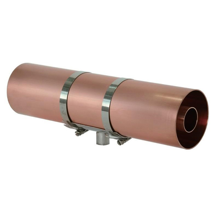
![Rigid Line Tubes for Rigid Coaxial Transmission Line]()
Tubi tal-Linja Riġida għal Linja ta 'Trażmissjoni Coaxial Riġida
Prezz (USD): Itlob għal kwotazzjoni
Mibjugħa: 156
-
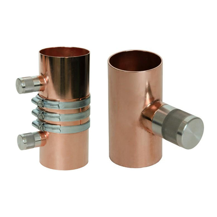
![Matching Sections for Coaxial Rigid Transmission Line]()
Sezzjonijiet li jaqblu għal Linja ta 'Trażmissjoni Coaxial Riġida
Prezz (USD): Itlob għal kwotazzjoni
Mibjugħa: 2,351
-
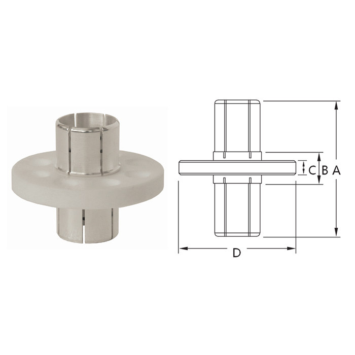
![Inner Support for Rigid Transmission Line]()
Appoġġ ta 'ġewwa għal Linja ta' Trażmissjoni Riġida
Prezz (USD): Itlob għal kwotazzjoni
Mibjugħa: 981
-
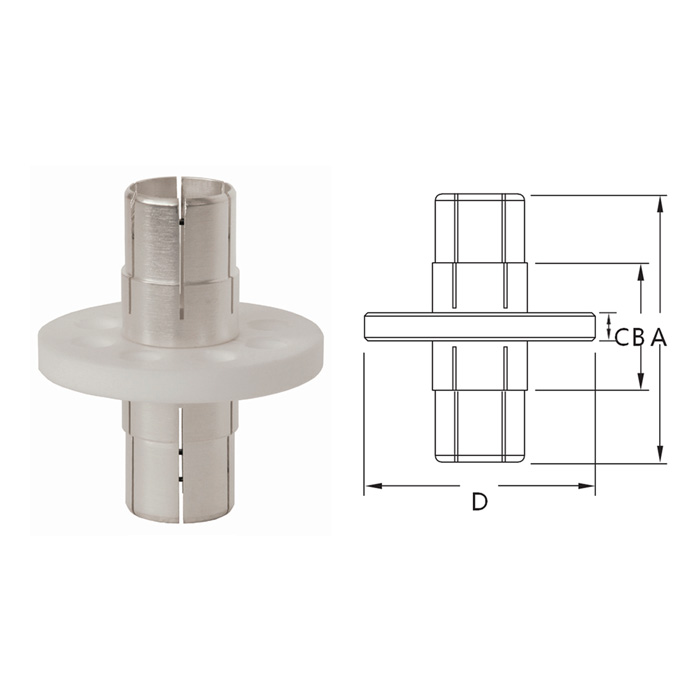
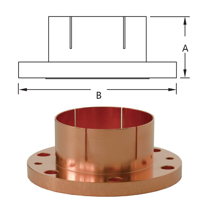
![Flange Inner Support for Rigid Transmission Line]()
Flanġ Appoġġ Intern għal Linja ta 'Trażmissjoni Riġida
Prezz (USD): Ikkuntattja għal aktar
Mibjugħa: 1,671
-
![Flange to Unflanged Adapter for Rigid Transmission Line]()
Flanġ għal Adapter Mhux Flanġ għal Linja ta 'Trażmissjoni Riġida
Prezz (USD): Itlob għal kwotazzjoni
Mibjugħa: 2,786
-
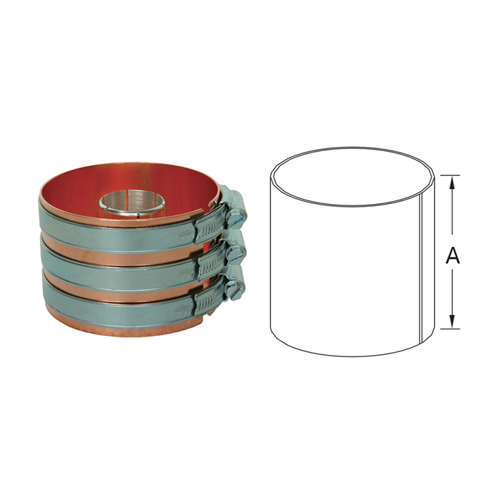
![Outer Sleeve for Rigid Transmission Line]()
Kmiem ta 'barra għal Linja ta' Trażmissjoni Riġida
Prezz (USD): Itlob għal kwotazzjoni
Mibjugħa: 1,798
-
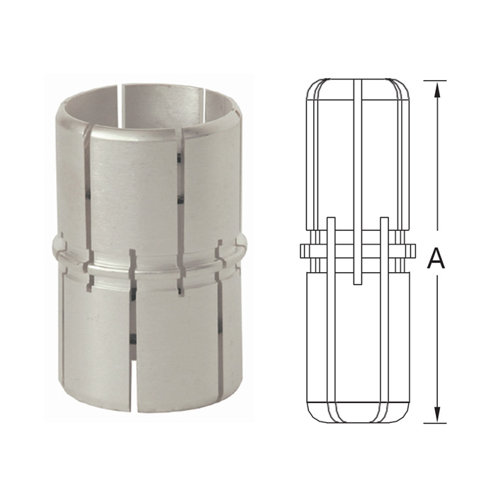
![Inner Bullet for Rigid Transmission Line]()
Bullet ta 'ġewwa għal Linja ta' Trażmissjoni Riġida
Prezz (USD): Itlob għal kwotazzjoni
Mibjugħa: 1,798
-
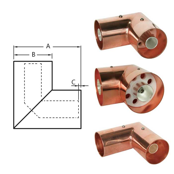
![Silver-plated Brass Elbows for Rigid Transmission Line Connection]()
Minkbejn tar-ram miksija bil-fidda għal Konnessjoni tal-Linja ta 'Trażmissjoni Riġida
Prezz (USD): Itlob għal kwotazzjoni
Mibjugħa: 1,498
-
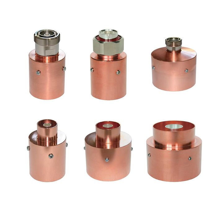
![Coaxial Adaptors for Rigid Transmission Line to Coaxial Cable Connection]()
Adapters Coaxial għal Linja ta 'Trażmissjoni Riġida għal Konnessjoni ta' Cable Coaxial
Prezz (USD): Itlob għal kwotazzjoni
Mibjugħa: 1,011
-
![Rigid Coaxial Transmission Line for FM, TV, and AM Station]()
Linja ta 'Trażmissjoni Coaxial riġida għal Stazzjon FM, TV, u AM
Prezz (USD): Itlob għal kwotazzjoni
Mibjugħa: 201
- X'inhuma t-terminoloġija komuni ta 'linja ta' trasmissjoni koassjali riġida?
- Hawn huma xi terminoloġiji ewlenin relatati ma 'linji ta' trasmissjoni koassjali riġidi fil-komunikazzjoni RF, flimkien ma 'ispjegazzjonijiet ta' xi jfissru dawn it-termini.
1. Dijametru ta 'barra (OD): Id-dijametru ta 'barra huwa l-kejl tad-dijametru tal-konduttur ta' barra tal-linja ta 'trasmissjoni. Tipikament ivarja minn ftit millimetri sa diversi ċentimetri, skont l-applikazzjoni.
2. Dijametru ta 'ġewwa (ID): Id-dijametru ta 'ġewwa huwa l-kejl tad-dijametru tal-konduttur ta' ġewwa tal-linja ta 'trażmissjoni. L-ID huwa tipikament ħafna iżgħar mill-OD, u huwa tipikament imkejjel f'millimetri.
3. Tul: It-tul ta 'linja ta' trasmissjoni koassjali riġida huwa d-distanza bejn iż-żewġ punti ta 'konnessjoni. It-tul huwa fattur importanti li għandek tikkonsidra meta tiddisinja sistema, peress li taffettwa l-ħin ġenerali tal-propagazzjoni u l-attenwazzjoni tas-sinjal.
4. Konduttur ta 'ġewwa: Dan huwa l-konduttur ċentrali tal-linja ta 'trażmissjoni, li ġeneralment tkun magħmula minn ram ta' konduttività għolja jew ram miksi bil-fidda. Il-konduttur ta 'ġewwa jservi biex iġorr is-sinjal elettriku tul it-tul tal-linja.
5. Konduttur ta 'barra: Dan huwa l-ilqugħ tal-metall ċilindriku li jdawwar il-konduttur ta 'ġewwa. Il-konduttur ta 'barra jservi biex jipprovdi lqugħ minn interferenza elettromanjetika u biex jirritorna s-sinjal elettriku għas-sors tiegħu.
6. Materjal Dielettriku: Il-materjal dielettriku huwa l-materjal iżolanti użat bejn il-kondutturi ta 'ġewwa u ta' barra, tipikament magħmul minn Teflon jew materjal simili. Il-kostanti dielettrika tal-materjal tiddetermina l-impedenza tal-linja.
7. Impedenza: L-impedenza hija miżura tar-reżistenza għall-fluss tal-kurrent elettriku. L-impedenza ta 'linja ta' trasmissjoni koassjali riġida hija tipikament 50 Ohms jew 75 Ohms, u hija determinata mill-ġeometrija u l-kostanti dielettrika tal-linja.
8. Medda ta 'frekwenza: Il-firxa ta 'frekwenza hija l-firxa ta' frekwenzi li fuqhom il-linja ta 'trażmissjoni tista' tittrasmetti sinjali b'telf baxx. Din il-firxa hija ddeterminata mid-dimensjonijiet u l-proprjetajiet materjali tal-linja.
9. Kapaċità tal-Immaniġġjar tal-Enerġija: Il-kapaċità tal-immaniġġjar tal-enerġija ta 'linja ta' trasmissjoni tirreferi għal-livell massimu ta 'qawwa li jista' jiġi trażmess permezz tal-linja mingħajr ħsara lill-linja jew komponenti oħra fis-sistema. Dan il-valur huwa determinat mid-daqs u l-materjal tal-linja.
10. Spiża: L-ispiża ta 'linja ta' trasmissjoni koassjali riġida tiddependi ħafna fuq id-dijametru, it-tul, it-tip ta 'materjal, u fatturi oħra msemmija hawn fuq. B'mod ġenerali, linji ta 'dijametru akbar u tulijiet itwal huma aktar għaljin, bħalma huma linji magħmula minn materjali ta' kwalità ogħla.
11. VSWR (Proporzjon ta' Mewġ Permanenti tal-Vultaġġ): VSWR hija miżura tal-proporzjon tal-amplitudni massima mal-amplitudni minima tas-sinjal f'linja ta 'trażmissjoni. Tindika kemm l-impedenza tal-linja taqbel mal-impedenza tas-sors u t-tagħbija. Valuri VSWR ta '1.5 jew inqas huma kkunsidrati tajbin għal ħafna applikazzjonijiet.
12. Telf ta 'Inserzjoni: Telf ta 'inserzjoni huwa l-ammont ta' qawwa tas-sinjal mitlufa meta sinjal jiġi trażmess permezz ta 'linja ta' trasmissjoni. Tipikament titkejjel f'decibels (dB) u tista' tiġi affettwata mit-tul, id-daqs, il-materjal u l-kwalità tal-linja. Telf ta 'inserzjoni aktar baxx huwa ġeneralment mixtieq għal sistemi ta' prestazzjoni għolja.
13. Veloċità tal-Propagazzjoni: Il-veloċità tal-propagazzjoni hija l-veloċità li biha mewġa elettromanjetika tivvjaġġa minn linja ta 'trażmissjoni. Tipikament titkejjel bħala frazzjoni tal-veloċità tad-dawl u tvarja skont it-tip ta 'materjal dielettriku użat fil-linja.
14. Daqs tal-ħanek: Id-daqs tal-ħanek jirreferi għad-daqs tal-ħanek tal-immuntar fuq kull tarf ta 'linja ta' trasmissjoni koassjali riġida. Dawn il-flanġijiet huma tipikament użati biex iwaħħlu l-linja ta 'trasmissjoni ma' komponenti oħra tas-sistema, bħal antenni jew amplifikaturi. Id-daqs u l-ispazjar tal-flanġijiet huma fatturi importanti li għandek tikkonsidra meta tiddisinja sistema.
15. Klassifikazzjoni tat-Temperatura: Il-klassifikazzjoni tat-temperatura ta 'linja ta' trasmissjoni tirreferi għat-temperatura massima jew minima li l-linja tista 'topera b'mod sikur. Din il-klassifikazzjoni hija determinata mit-tip ta 'materjal użat fil-linja u l-punt tat-tidwib jew tat-tqassim tiegħu.
16. Terminoloġija Speċifika għall-Applikazzjoni: Fl-aħħar nett, hemm xi terminoloġiji jew speċifikazzjonijiet oħra li jistgħu jkunu speċifiċi għal ċerti applikazzjonijiet ta 'linji ta' trasmissjoni koassjali riġidi. Pereżempju, ċerti linji ta 'trażmissjoni jista' jkollhom forma jew kurvatura unika, jew jistgħu jkunu magħmula minn tip speċifiku ta 'materjal biex jissodisfaw rekwiżiti ambjentali speċifiċi. Huwa importanti li jitqiesu l-ispeċifikazzjonijiet u r-rekwiżiti rilevanti kollha għal applikazzjoni partikolari meta tagħżel linja ta 'trażmissjoni.
17. Veloċità tal-Fażi: Il-veloċità tal-fażi hija r-rata li biha l-fażi ta 'mewġa sinusojdali tippropaga permezz ta' linja ta 'trażmissjoni. Huwa definit bħala l-proporzjon tal-frekwenza tal-mewġ mal-wavelength, u huwa dipendenti fuq il-kostanti dielettrika u l-permeabilità manjetika tal-materjali użati fil-linja ta 'trasmissjoni.
18. Attenwazzjoni: L-attenwazzjoni hija t-tnaqqis fl-amplitudni ta 'sinjal hekk kif jivvjaġġa 'l isfel minn linja ta' trażmissjoni. Hija kkawżata minn diversi fatturi, inklużi telf manjetiku u dielettriku, telf reżistenti, u telf radjattiv, fost oħrajn. L-ammont ta 'attenwazzjoni jiddependi fuq il-frekwenza u t-tul tal-linja ta' trasmissjoni, kif ukoll il-materjali użati.
19. Veloċità tal-Grupp: Il-veloċità tal-grupp hija r-rata li biha l-envelope ta' pakkett tal-mewġ jippropaga permezz ta' linja ta' trażmissjoni. Huwa determinat mill-karatteristiċi ta 'dispersjoni tal-materjali użati fil-linja. Il-veloċità tal-grupp hija importanti biex wieħed jifhem kemm l-informazzjoni tista 'tiġi trażmessa malajr permezz ta' linja ta 'trażmissjoni.
20. Varjazzjoni ta' Telf ta' Inserzjoni (ILV): L-ILV hija kejl tal-varjazzjoni fit-telf tal-inserzjoni fuq medda ta' frekwenza partikolari. Jipprovdi informazzjoni dwar il-konsistenza tal-prestazzjoni tal-linja ta 'trasmissjoni taħt kundizzjonijiet differenti u huwa importanti għal applikazzjonijiet li jeħtieġu trasmissjoni preċiża tas-sinjal.
21. Klassifikazzjonijiet Ambjentali: Skont l-applikazzjoni, linja ta 'trasmissjoni koassjali riġida jista' jkollha bżonn tissodisfa klassifikazzjonijiet ambjentali speċifiċi, bħal klassifikazzjonijiet ta 'protezzjoni tal-ingress (IP) għar-reżistenza għall-ilma u t-trab, jew screenings tal-istress ambjentali (ESS) għal reżistenza għall-vibrazzjoni u ċ-ċikliżmu tat-temperatura. Dawn il-klassifikazzjonijiet jistgħu jaffettwaw l-għażla tal-materjali u l-proċessi tal-manifattura użati fil-linja ta 'trażmissjoni.
22. Kit ta 'kalibrazzjoni: Kit ta 'kalibrazzjoni huwa sett ta' standards ta 'kejl użat biex jikkalibra analizzatur tan-netwerk tal-vettur (VNA) għal kejl preċiż tal-prestazzjoni tal-linja ta' trażmissjoni. Il-kit jista 'jinkludi komponenti bħal ċirkwit miftuħ, ċirkwit qasir, u standards ta' impedenza biex jiżguraw kejl preċiż ta 'VSWR, telf ta' inserzjoni, u parametri oħra.
23. Stabbiltà tal-Frekwenzi: L-istabbiltà tal-frekwenza tirreferi għall-kapaċità ta 'linja ta' trasmissjoni li żżomm il-karatteristiċi ta 'trażmissjoni tagħha matul iż-żmien u taħt kundizzjonijiet ambjentali li jvarjaw. Fatturi bħat-temperatura, pressjoni u umdità jistgħu jaffettwaw l-istabbiltà tal-prestazzjoni ta 'linja ta' trasmissjoni, u jagħmlu l-istabbiltà tal-frekwenza konsiderazzjoni importanti għal applikazzjonijiet ta 'preċiżjoni għolja.
24. Ċaqliq tal-Fażi: Il-bidla fil-fażi tkejjel id-differenza fl-angolu tal-fażi bejn is-sinjali tad-dħul u tal-ħruġ ta 'linja ta' trasmissjoni. Huwa affettwat minn fatturi bħall-frekwenza, it-tul, u l-materjali użati fil-linja.
25. Effettività tal-Ilqugħ: L-effettività tal-ilqugħ hija miżura tal-kapaċità tal-konduttur ta 'barra ta' linja ta 'trażmissjoni li jipproteġi l-konduttur ta' ġewwa minn interferenza elettromanjetika. Livelli ogħla ta 'effettività tal-ilqugħ huma ġeneralment preferuti, speċjalment għal applikazzjonijiet sensittivi.
26. Tip ta 'Konnettur Standard: Tip ta 'konnettur standard huwa tip komuni ta' konnettur użat biex iwaħħal linja ta 'trażmissjoni ma' komponenti oħra f'sistema ta 'komunikazzjoni RF. Eżempji ta 'tipi ta' konnetturi standard jinkludu konnetturi tat-tip SMA, BNC u N.
27. Raġġ tal-liwja: Ir-raġġ tal-liwja huwa r-raġġ minimu f'punti fejn linja ta 'trasmissjoni koassjali riġida hija mgħawġa. Dan il-valur huwa importanti li jiġi kkunsidrat meta tinstalla linja ta 'trasmissjoni, peress li tgħawwiġ eċċessiv jista' jikkawża degradazzjoni fil-prestazzjoni.
28. Tqabbil tal-impedenza: It-tqabbil tal-impedenza huwa l-proċess li jiżgura li l-impedenza ta 'linja ta' trasmissjoni taqbel mal-impedenza ta 'komponenti oħra fis-sistema, bħal amplifikatur jew antenna. Diskrepanzi ta 'impedenza jistgħu jikkawżaw riflessjonijiet u kwistjonijiet oħra li jistgħu jiddegradaw il-prestazzjoni tas-sistema.
- Liema partijiet u aċċessorji huma meħtieġa għal linji ta 'trasmissjoni koassjali riġidi?
- Il-partijiet u l-aċċessorji kompluti ta’ linja ta’ trażmissjoni koassjali riġida għal sistema ta’ xandir RF jistgħu jinkludu l-komponenti li ġejjin:
1. Linja koassjali: Dan huwa l-komponent ewlieni tal-linja ta 'trażmissjoni li jikkonsisti f'konduttur ta' barra tar-ram solidu u konduttur ta 'ġewwa tar-ram vojt. Jintuża biex jittrasmetti sinjali RF ta 'qawwa għolja mis-sors għall-antenna.
2. Flanġijiet: Dawn huma l-konnetturi tal-metall li jintużaw biex jingħaqdu mal-linja koassjali ma 'komponenti oħra bħat-trasmettitur, ir-riċevitur u l-antenna.
3. Konduttur ta 'ġewwa: Dan huwa l-pajp tar-ram vojt li jestendi miċ-ċentru tal-linja koassjali u jġorr is-sinjal RF.
4. Materjal dielettriku: Dan huwa materjal mhux konduttiv li jintuża biex jissepara l-kondutturi ta 'ġewwa u ta' barra tal-linja koassjali. Jgħin biex tinżamm l-impedenza tal-linja u jnaqqas it-telf tas-sinjal.
5. Konduttur ta 'barra: Dan huwa tubu tar-ram solidu li jdawwar il-materjal dielettriku u jipprovdi lqugħ minn interferenza esterna.
6. Kitts tal-ert: Dawn il-kits huma wżati għall-art tal-linja ta 'trasmissjoni koassjali biex jipproteġuha minn strajks tad-dawl u żidiet elettriċi oħra.
7. Attenwaturi: Dawn huma apparati passivi li jintużaw biex inaqqsu l-amplitudni tas-sinjal RF fil-linja koassjali. Jintużaw biex iqabblu l-impedenza tal-linja ta 'trasmissjoni ma' dik tal-antenna.
8. Couplers: Dawn huma apparati passivi użati biex jaqsmu jew jgħaqqdu sinjali RF fil-linja koassjali. Jintużaw biex iwasslu sinjali RF għal antenni multipli.
9. Terminaturi: Dawn huma apparati passivi li jintużaw biex itemmu l-linja koassjali meta ma tkunx qed tintuża. Jgħinu biex jipprevjenu riflessjonijiet u telf tas-sinjal.
10. Waveguide adapters: Dawn huma komponenti użati biex jingħaqdu linja koassjali ma 'waveguide, li tintuża biex tittrasmetti sinjali ta' frekwenza ogħla.
B'mod ġenerali, il-komponenti ta 'linja ta' trasmissjoni koassjali riġida għal sistema ta 'xandir RF huma ddisinjati biex jiżguraw kwalità tajba tas-sinjal, jimminimizzaw it-telf tas-sinjal, u jipproteġu s-sistema minn ħsara minħabba żidiet esterni u interferenza.
- X'inhuma l-applikazzjonijiet komuni ta 'linja ta' trasmissjoni koassjali riġida?
- Linji ta 'trasmissjoni koassjali riġidi ħafna drabi jintużaw f'applikazzjonijiet ta' komunikazzjoni RF li jeħtieġu tqandil ta 'qawwa għolja u telf ta' sinjal baxx. Hawn huma xi applikazzjonijiet komuni ta 'linji ta' trasmissjoni koassjali riġidi:
1. Xandir: Linji ta 'trasmissjoni koassjali riġidi huma komunement użati f'applikazzjonijiet ta' xandir biex jittrasmettu sinjali RF ta 'qawwa għolja mit-trasmettitur għall-antenna. Huma joffru telf ta 'sinjal baxx u kapaċità ta' mmaniġġjar ta 'enerġija għolja, li jagħmluhom għażla popolari għax-xandir bir-radju u t-televiżjoni.
2. Komunikazzjoni bis-satellita: Linji ta 'trasmissjoni koassjali riġidi jintużaw ukoll f'sistemi ta' komunikazzjoni bis-satellita biex jittrasmettu u jirċievu sinjali bejn is-satellita u l-istazzjon tal-art. Il-kapaċità tal-immaniġġjar ta 'qawwa għolja ta' linji ta 'trasmissjoni koassjali riġidi hija partikolarment utli għat-trażmissjoni ta' sinjali lejn u minn satelliti orbitanti.
3. Tagħmir mediku: Linji ta 'trasmissjoni koassjali riġidi jintużaw f'tagħmir mediku bħal magni MRI, skaners CT, u tagħmir ieħor ta' immaġini dijanjostiċi. It-telf ta 'sinjal baxx u l-kapaċità ta' mmaniġġjar ta 'qawwa għolja ta' linji ta 'trażmissjoni koassjali riġidi jgħinu biex jiżguraw immaġini preċiżi u affidabbli.
4. Militari u difiża: Linji ta 'trasmissjoni koassjali riġidi jintużaw f'applikazzjonijiet militari u ta' difiża bħal sistemi tar-radar, sistemi ta 'komunikazzjoni, u gwerra elettronika. Il-kapaċità tal-immaniġġjar ta 'qawwa għolja ta' linji ta 'trażmissjoni koassjali riġidi tagħmilhom adattati għall-immaniġġjar tal-livelli ta' qawwa għolja użati f'applikazzjonijiet militari u ta 'difiża.
5. Applikazzjonijiet industrijali: Linji ta 'trasmissjoni koassjali riġidi jintużaw f'applikazzjonijiet industrijali bħal qtugħ tal-plażma, iwweldjar, u tisħin ta' induzzjoni. It-telf ta 'sinjal baxx u l-kapaċità ta' mmaniġġjar ta 'qawwa għolja jagħmluhom ideali għat-trażmissjoni ta' sinjali RF ta 'frekwenza għolja użati fi proċessi industrijali.
6. Komunikazzjoni bla fili: Linji ta 'trasmissjoni koassjali riġidi jintużaw ukoll f'sistemi ta' komunikazzjoni mingħajr fili bħal netwerks ċellulari u links microwave minn punt għal punt. Jintużaw biex jittrasmettu sinjali RF bejn stazzjonijiet bażi u komponenti oħra fin-netwerk.
7. Riċerka u żvilupp: Linji ta 'trasmissjoni koassjali riġidi ħafna drabi jintużaw f'applikazzjonijiet ta' riċerka u żvilupp bħall-karatterizzazzjoni tal-materjal, l-ittestjar tal-microwave, u l-ittestjar tal-kompatibilità elettromanjetika. Jintużaw biex jittrasmettu sinjali RF bejn it-tagħmir tat-test u l-apparat jew is-sistema li qed tiġi ttestjata.
8. Komunikazzjoni bl-avjazzjoni: Linji ta 'trażmissjoni koassjali jintużaw ukoll f'sistemi ta' komunikazzjoni tal-avjazzjoni bħal sistemi tar-radar u tan-navigazzjoni. It-telf ta 'sinjal baxx u l-kapaċità ta' mmaniġġjar ta 'qawwa għolja ta' linji ta 'trażmissjoni koassjali riġidi jagħmluhom adattati għall-immaniġġjar tal-livelli ta' qawwa għolja użati f'dawn is-sistemi.
Fil-qosor, linji ta 'trażmissjoni koassjali riġidi jintużaw f'firxa wiesgħa ta' applikazzjonijiet li jeħtieġu immaniġġjar ta 'qawwa għolja u telf ta' sinjal baxx. Huma komunement użati fix-xandir, komunikazzjoni bis-satellita, tagħmir mediku, militari u difiża, applikazzjonijiet industrijali, komunikazzjoni mingħajr fili, riċerka u żvilupp, komunikazzjoni tal-avjazzjoni.
- X'inhuma l-istrutturi komuni ta 'linja ta' trasmissjoni koassjali riġida?
- L-istrutturi komuni ta 'linja ta' trasmissjoni koassjali riġida użata fil-komunikazzjoni RF jinkludu dan li ġej:
1. Linja koassjali: Il-linja koassjali hija l-komponent ewlieni tal-linja ta 'trasmissjoni. Tikkonsisti f'konduttur ta 'barra tar-ram solidu u konduttur ta' ġewwa tar-ram vojt. Iż-żewġ kondutturi huma separati minn materjal dielettriku bħal arja, Teflon, jew ċeramika. Il-linja koassjali hija mfassla biex tittrasmetti sinjali ta 'frekwenza għolja b'telf ta' sinjal baxx.
2. Bullet ta' ġewwa: Il-bullet ta 'ġewwa, magħruf ukoll bħala l-appoġġ ta' ġewwa, huwa komponent tal-ħanek. Huwa konnettur maskili li jisporġi 'l barra li jestendi mit-tarf tal-linja koassjali u fih pin ta' ġewwa li jgħaqqad mal-parti femminili tal-flanġ. Il-bullet ta 'ġewwa huwa ddisinjat biex iżomm l-ispazjar xieraq bejn il-kondutturi ta' ġewwa u ta 'barra tal-linja koassjali.
3. kmiem ta 'barra: Il-kmiem ta 'barra huwa l-komponent femminili tal-ħanek. Hija tidħol fuq it-tarf tal-linja koassjali u hija mwaħħla fil-post permezz ta 'boltijiet. Il-kmiem ta 'barra tikkompressa l-appoġġ ta' ġewwa kontra l-konduttur ta 'ġewwa tal-linja koassjali biex toħloq konnessjoni sigura u ta' telf baxx.
4. Minkbejn: Il-minkbejn huma sezzjonijiet milwija ta 'linja koassjali li jintużaw biex jibdlu d-direzzjoni tal-linja ta' trasmissjoni mingħajr ma jġarrbu telf kbir. Il-minkbejn huma tipikament iddisinjati biex ikollhom raġġ ta 'liwja li jaqbel mal-bqija tal-linja ta' trasmissjoni biex tiġi żgurata trasmissjoni ta 'telf baxx.
5. Assemblaġġi tat-Tee: Assemblaġġi Tee huma użati biex jaqsmu jew jgħaqqdu sinjali RF fil-linja koassjali. Huma ddisinjati f'forma ta 'T u jista' jkollhom portijiet multipli ta 'input u output skond l-applikazzjoni.
6. Reducers: Reducers jintużaw biex jaqblu mad-daqs ta 'konnettur fuq il-linja koassjali mad-daqs tal-komponent li jkun qed jgħaqqad miegħu.
7. Flanġijiet: Il-flanġijiet huma l-konnetturi tal-metall li jintużaw biex jingħaqdu mal-linja koassjali ma 'komponenti oħra bħat-trasmettitur, ir-riċevitur u l-antenna. Tipikament jikkonsistu f'appoġġ ta 'ġewwa, kmiem ta' barra, bullet ta 'ġewwa, u minkbejn.
8. Barriera tal-gass: Il-barrieri tal-gass jintużaw biex jipprevjenu l-gassijiet milli jidħlu fil-linja ta 'trażmissjoni, li jistgħu jikkawżaw attenwazzjoni u degradazzjoni tas-sinjal. Huma magħmula minn materjali bħal Teflon u huma ddisinjati biex iżommu l-ambjent taħt pressjoni tal-linja ta 'trażmissjoni.
9. Konnettur iżolatur tal-ankra: Konnetturi tal-iżolaturi tal-ankri jintużaw biex jissospendu l-linja koassjali minn struttura ta 'appoġġ bl-użu ta' iżolaturi tal-ankri. Huma jikkonsistu minn bracket tal-metall li jeħel mal-iżolatur u bolt li jassigura l-linja koassjali mal-parentesi.
10. Flanġ tal-għalqae: Flanġijiet tal-kamp huma flanġijiet speċjalizzati użati f'installazzjonijiet fuq il-post li jippermettu installazzjoni ta 'malajr u faċli mingħajr ma jeħtieġu għodda jew tagħmir speċjalizzat. Huma tipikament iddisinjati biex ikunu ħfief u faċli biex jimmaniġġaw.
11. Pjanċa tal-ankra tal-ħajt: Pjanċi tal-ankri tal-ħajt jintużaw biex iwaħħlu b'mod sikur il-linja koassjali ma 'ħajt jew wiċċ ieħor. Tipikament huma magħmula mill-metall u għandhom toqob ta 'bolt multipli għat-twaħħil.
12. Hangers: Hangers jintużaw biex jissospendu l-linja koassjali minn struttura ta 'appoġġ bħal torri jew arblu. Huma ddisinjati biex jifilħu r-riħ u tagħbijiet mekkaniċi u jistgħu jiġu ffissati jew mgħobbija bir-rebbiegħa biex jipprovdu flessibilità.
13. Patch panels: Patch panels jintużaw biex iqassmu sinjali RF għal komponenti multipli u tipikament jinkludu portijiet multipli għall-input u l-ħruġ. Jistgħu jkunu fissi jew modulari u huma ddisinjati biex jimminimizzaw it-telf tas-sinjal.
B'mod ġenerali, l-istrutturi komuni ta 'linja ta' trasmissjoni koassjali riġida użata fil-komunikazzjoni RF jinkludu firxa ta 'komponenti li huma ddisinjati biex jiżguraw kwalità tajba tas-sinjal, jimminimizzaw it-telf tas-sinjal, u jipproteġu s-sistema minn ħsara minħabba kundizzjonijiet ambjentali u tagħbijiet mekkaniċi.
- Kif tuża u żżomm b'mod korrett linja ta 'trasmissjoni koassjali riġida?
- Biex jiġi żgurat l-użu u l-manutenzjoni korretti ta 'linja ta' trasmissjoni koassjali riġida użata fil-komunikazzjoni RF, għandhom jiġu kkunsidrati l-pariri li ġejjin:
1. Installazzjoni xierqa: Kun żgur li l-linja koassjali hija installata kif suppost u b'mod sigur, u tnaqqas l-istress fuq il-linja u l-konnessjonijiet.
2. Evita liwi żejjed: Il-liwja żejda tal-linja koassjali tista 'tikkawża telf u degradazzjoni tas-sinjal. Kun żgur li r-raġġ tal-liwja ma jaqbiżx il-limitu rakkomandat.
3. Uża Konnetturi Proper: Uża l-konnetturi xierqa għal-linja koassjali u żgura li huma ssikkati sew biex jipprevjenu t-telf tas-sinjal minħabba konnessjonijiet laxki.
4. L-ert kif suppost: Żgura li l-linja koassjali u l-komponenti l-oħra kollha jkunu msejsa sew fuq l-art biex tevita ħsara potenzjali minn sajjetti jew avvenimenti elettriċi oħra. Is-sistema ta 'l-ert għandha tiġi spezzjonata regolarment għal kwalunkwe sinjal ta' ħsara u miżmuma kif meħtieġ.
5. Spezzjonijiet regolari: Il-linja koassjali, il-konnetturi, u komponenti oħra għandhom jiġu spezzjonati regolarment għal sinjali ta 'korrużjoni jew ħsara. Kwalunkwe ħsara għandha tiġi indirizzata fil-pront biex tiġi evitata d-degradazzjoni jew in-nuqqas tas-sinjal.
6. Protezzjoni Ambjentali: Linji koassjali għandhom ikunu protetti minn fatturi ambjentali bħall-umdità, ħmieġ, u temperaturi estremi. L-użu ta 'għata protettiva u materjali reżistenti għat-temp jistgħu jgħinu biex tiġi evitata l-ħsara minn dawn il-fatturi.
7. Tindif regolari: It-tindif regolari tal-konnetturi u komponenti oħra jista 'jipprevjeni l-akkumulazzjoni ta' trab u debris li jistgħu jikkawżaw telf u degradazzjoni tas-sinjal.
8. Ittestjar regolari: Ittestjar regolari tal-komponenti tal-linja koassjali u tas-sistema jistgħu jgħinu biex jidentifikaw kwalunkwe kwistjoni qabel ma jirriżultaw f'degradazzjoni jew falliment tas-sinjal.
Billi ssegwi dawn il-pariri, il-ħajja ta 'linja ta' trasmissjoni koassjali riġida tista 'tiġi estiża u s-sistema tista' tkompli tipprovdi komunikazzjoni RF affidabbli u ta 'kwalità għolja.
- X'inhuma l-aktar speċifikazzjonijiet importanti ta 'linja ta' trasmissjoni koassjali riġida?
- L-aktar speċifikazzjonijiet fiżiċi u RF importanti ta 'linja ta' trasmissjoni koassjali riġida użata fil-komunikazzjoni RF jinkludu dan li ġej:
1. Impedenza: L-impedenza karatteristika tal-linja ta 'trażmissjoni tiddetermina l-ammont ta' telf ta 'sinjal u riflessjoni li jseħħ fil-linja. Valuri komuni għal linji ta 'trasmissjoni koassjali jinkludu 50 ohms, 75 ohms, u 90 ohms.
2. Medda ta 'frekwenza: Il-firxa tal-frekwenza ta 'linja ta' trasmissjoni koassjali tiddetermina l-firxa ta 'frekwenzi li jistgħu jiġu trażmessi b'telf ta' sinjal baxx. Applikazzjonijiet ta 'frekwenza għolja jistgħu jeħtieġu linji koassjali speċjalizzati jew ta' prestazzjoni għolja.
3. Telf ta 'Inserzjoni: It-telf ta 'inserzjoni ta' linja ta 'trażmissjoni koassjali jispeċifika l-ammont ta' telf ta 'sinjal li jseħħ meta s-sinjal jgħaddi mill-linja. Telf baxx ta 'inserzjoni huwa kruċjali għal komunikazzjoni RF ta' kwalità għolja u affidabbli.
4. VSWR: Il-proporzjon tal-mewġ permanenti tal-vultaġġ (VSWR) jispeċifika l-ammont ta 'riflessjoni tas-sinjal li jseħħ fil-linja ta' trażmissjoni. Valuri għolja VSWR jistgħu jikkawżaw degradazzjoni tas-sinjal u jistgħu jagħmlu ħsara lill-komponenti RF sensittivi.
5. Kapaċità tal-Immaniġġjar tal-Enerġija: Il-kapaċità tal-immaniġġjar tal-enerġija ta 'linja ta' trasmissjoni koassjali tispeċifika l-ammont massimu ta 'enerġija li tista' tiġi trażmessa b'mod sikur permezz tal-linja. Din l-ispeċifikazzjoni hija kruċjali għal applikazzjonijiet RF ta 'qawwa għolja.
6. Tul u Dijametru tal-Cable: It-tul u d-dijametru ta 'linja ta' trasmissjoni koassjali jistgħu jaffettwaw it-telf tas-sinjal u t-telf ta 'inserzjoni tal-linja. It-tul u d-dijametru għandhom jintgħażlu abbażi tar-rekwiżiti speċifiċi tal-applikazzjoni.
7. Kostanti Dielettriċi: Il-kostanti dielettrika tal-materjal iżolanti tal-linja koassjali taffettwa l-impedenza karatteristika u l-veloċità tat-trażmissjoni tal-linja. Materjali komuni użati jinkludu arja, Teflon, u ċeramika.
8. Tip ta 'konnettur: It-tip ta 'konnettur użat mal-linja ta' trasmissjoni koassjali għandu jkun xieraq għall-applikazzjoni speċifika u għandu jkollu telf ta 'inserzjoni baxx u VSWR.
9. Firxa tat-Temperatura Operattiva: Il-firxa tat-temperatura operattiva tal-linja ta 'trażmissjoni koassjali għandha tkun xierqa għall-applikazzjoni speċifika sabiex tevita d-degradazzjoni tas-sinjal jew il-ħsara lill-linja.
B'mod ġenerali, l-għażla ta 'linja ta' trażmissjoni koassjali bi speċifikazzjonijiet xierqa għall-applikazzjoni speċifika ta 'komunikazzjoni RF tiżgura l-aħjar prestazzjoni u affidabilità.
- Kif tagħżel l-aħjar linji ta 'trasmissjoni koassjali riġidi għall-istazzjon tar-radju FM?
- Meta tagħżel linja ta 'trażmissjoni koassjali riġida għal stazzjon tar-radju FM, hemm diversi fatturi li għandek tikkonsidra bbażati fuq il-produzzjoni tal-enerġija, it-tul, il-firxa tal-frekwenza, it-tip ta' konnettur u l-aċċessorji meħtieġa.
1. Stazzjon tar-radju FM b'enerġija baxxa: Għal stazzjonijiet tar-radju FM ta 'enerġija baxxa b'outputs ta' enerġija inqas minn 50 watts, linja ta 'trażmissjoni koassjali riġida ta' 1/2 pulzier jew 7/8 pulzier iżgħar u bi prezz aktar baxx hija rakkomandata b'impedenza ta '50 ohms. Dawn il-kejbils joffru telf ta 'sinjal baxx u huma disponibbli b'tipi ta' konnetturi komuni inklużi konnetturi BNC jew N-Type. Aċċessorji bħal klampi tal-kejbils, kits tal-ert, u blokki tat-terminazzjoni jistgħu wkoll ikunu meħtieġa kif ukoll kejbils tal-jumpers.
2. Stazzjon tar-radju FM ta 'qawwa medja: Għal stazzjonijiet tar-radju FM ta 'qawwa medja b'outputs ta' enerġija li jvarjaw minn 50 sa 1000 watts, hija rakkomandata linja ta 'trasmissjoni koassjali riġida li timmaniġġa qawwa akbar u ogħla bħal 1-5/8 pulzier jew 3-1/8 pulzier serje-coax. Dawn il-kejbils joffru telf ta 'sinjal baxx u kapaċità ogħla għall-immaniġġjar tal-enerġija, meta mqabbla ma' kejbils iżgħar. Il-konnetturi użati f'dan il-każ jistgħu jkunu konnetturi tal-flanġ tat-tip N, 7/16 DIN jew EIA. Aċċessorji meħtieġa jistgħu jinkludu jumper cables, splices, surge arrestors, kits ta 'l-ert, u arrestors tas-sajjetti.
3. Stazzjon tar-Radju FM ta 'Qawwa Għolja: Għal stazzjonijiet tar-radju FM ta 'qawwa għolja b'outputs ta' enerġija ogħla minn 1000 watt, jistgħu jkunu meħtieġa linji ta 'trasmissjoni koassjali riġidi akbar bħal 4-1/16 pulzier jew 6-1/8 pulzieri serje-coax. Id-dijametru akbar ta 'dawn il-kejbils jgħin biex jitnaqqas it-telf tas-sinjal u jipprovdi l-aħjar kwalità tas-sinjal. Konnetturi tal-ħanek tat-tip N, 7/16 DIN jew EIA huma komunement użati f'applikazzjonijiet ta 'qawwa għolja. Aċċessorji meħtieġa jistgħu jinkludu dehydrators, splices, sistemi ta 'tkessiħ, kejbils tal-ġumpers u blokki tat-terminazzjoni.
It-tul tal-linja ta 'trasmissjoni koassjali riġida għandu jintgħażel ibbażat fuq id-distanza bejn it-trasmettitur u l-antenna, u l-ispeċifikazzjonijiet tal-kejbil. Tulijiet tal-kejbil itwal jirriżultaw f'telf ta 'sinjal ogħla għalhekk it-tul għandu jinżamm għall-minimu. Għandha tingħata attenzjoni bir-reqqa lill-kapaċità tal-immaniġġjar tal-enerġija tal-kejbil magħżul biex jiġi żgurat li jkun jista 'jimmaniġġja l-output tal-enerġija meħtieġ.
B'mod ġenerali, l-għażla tal-linja ta 'trażmissjoni koassjali riġida t-tajba għal stazzjon tar-radju FM tiddependi fuq fatturi bħall-output tal-enerġija, it-tul, il-firxa tal-frekwenza, it-tip ta' konnettur u l-aċċessorji meħtieġa. L-għażla tal-kejbil u l-aċċessorji t-tajba tiżgura l-aħjar prestazzjoni, affidabbiltà u kwalità tas-sinjal.
- Kif tagħżel l-aħjar linji ta 'trasmissjoni koassjali riġidi għall-istazzjon tax-xandir AM?
- Meta tagħżel linja ta 'trażmissjoni koassjali riġida għal stazzjon tax-xandir AM, għandhom jiġu kkunsidrati diversi fatturi, bħall-output tal-enerġija, il-firxa tal-frekwenza, it-tul tal-linja, it-tip ta' konnettur u l-aċċessorji meħtieġa.
1. Stazzjon tax-Xandir AM b'Enerġija Baxxa: Għal stazzjon tax-xandir AM ta 'qawwa baxxa, tista' tintuża linja ta 'trasmissjoni koassjali riġida ta' 7/8 pulzier jew 1/2 pulzier iżgħar u bi prezz aktar baxx b'impedenza ta '50 ohms. Dawn il-kejbils jistgħu jimmaniġġjaw outputs ta 'enerġija sa 5 kilowatts u huma għażla ideali għal stazzjonijiet tax-xandir AM fuq skala żgħira b'output ta' enerġija aktar baxx. Il-konnetturi użati f'dan il-każ jistgħu jkunu tipi ta 'konnettur komunement disponibbli bħal N-type jew BNC.
It-tul tal-linja ta 'trasmissjoni koassjali riġida għal stazzjon tax-xandir AM ta' qawwa baxxa għandu jinżamm qasir kemm jista 'jkun biex jimminimizza t-telf tas-sinjal. Linji ta 'trasmissjoni koassjali riġidi b'impedenza karatteristika aktar baxxa jistgħu jintużaw għal applikazzjonijiet ta' enerġija baxxa. Dawn il-kejbils joffru trasmissjoni aħjar tas-sinjal, u t-tqabbil tal-impedenza jista 'wkoll jgħin biex itejjeb il-kwalità tas-sinjal.
F'termini ta 'aċċessorji għal stazzjon tax-xandir AM ta' qawwa baxxa, ikun jiddependi fuq ir-rekwiżiti speċifiċi tal-istazzjon. Fil-biċċa l-kbira tal-każijiet, kejbils tal-jumpers, kits tal-ert, u blokki tat-terminazzjoni, u dehydrator huma aċċessorji importanti. Dawn l-aċċessorji huma meħtieġa biex inaqqsu t-telf tas-sinjal, inaqqsu l-istorbju, u jipprovdu protezzjoni għal-linja ta 'trażmissjoni.
2. Stazzjon tax-Xandir AM ta' Qawwa Medju: Għal stazzjonijiet tax-xandir AM ta 'qawwa medja, linja ta' trasmissjoni koassjali riġida standard ta '50 ohm 1-5/8 pulzier jew 3 pulzieri tintuża komunement. Dawn il-kejbils huma ddisinjati biex jimmaniġġjaw outputs ta 'enerġija moderata li jvarjaw bejn 5 u 50 kilowatts. Il-konnetturi użati f'dan il-każ jistgħu jkunu konnetturi tal-flanġ UHF, N-Type jew EIA.
3. Stazzjon tax-Xandir AM ta 'Qawwa Għolja: Għal stazzjonijiet tax-xandir AM ta' qawwa għolja, trid tintgħażel linja ta' trażmissjoni koassjali riġida li tkun kapaċi timmaniġġja outputs ta' qawwa għolja li jaqbżu l-50 kilowatt. Kejbils użati għal applikazzjonijiet ta 'xandir AM ta' qawwa għolja jinkludu linji koassjali riġidi ta '4-1/16 pulzier jew 6-1/4 pulzier bi transformers li jaqblu mal-impedenza. Dawn il-kejbils għandhom telf ta 'sinjal aktar baxx u jistgħu jimmaniġġjaw livelli ta' qawwa ogħla minn kejbils iżgħar. Il-konnetturi użati f'dan il-każ jistgħu jkunu konnetturi tal-flanġ tat-Tip N jew EIA.
Il-kapaċità tal-immaniġġjar tal-enerġija tal-kejbil magħżul hija kritika meta tagħżel linja ta 'trasmissjoni koassjali riġida għal stazzjon tax-xandir AM. It-telf tas-sinjal huwa wkoll fattur essenzjali li għandu jiġi kkunsidrat peress li d-degradazzjoni tas-sinjal tista 'sseħħ fuq tul ta' tulijiet itwal tal-kejbil. Għażla bir-reqqa ta 'konnetturi u aċċessorji hija meħtieġa wkoll biex jiġu evitati problemi bħal interferenza u tnixxija tas-sinjali.
Fatturi oħra li għandek tikkonsidra meta tagħżel linja ta 'trasmissjoni koassjali riġida għal stazzjon tax-xandir AM huma t-tul tal-linja u l-firxa tal-frekwenza. It-tul tal-kejbil għandu jinżamm għall-minimu biex jitnaqqas it-telf tas-sinjal. Linji ta 'trasmissjoni koassjali riġidi b'impedenza karatteristika aktar baxxa, bħal 50 ohms, ħafna drabi huma preferibbli għal applikazzjonijiet ta' xandir AM. It-tqabbil tal-impedenza tas-sinjal huwa importanti wkoll biex jiġi żgurat li t-trażmissjoni tas-sinjal tkun ottima.
Aċċessorji għal linja ta 'trażmissjoni koassjali riġida jistgħu jinkludu kejbils ta' jumper, konnetturi, surge arrestors, kits ta 'l-ert, arrestors tas-sajjetti u blokki tat-terminazzjoni. Dawn l-aċċessorji huma meħtieġa biex jiżguraw installazzjoni xierqa, kwalità tas-sinjal, u protezzjoni tas-sinjal.
B'mod ġenerali, l-għażla ta 'linja ta' trasmissjoni koassjali riġida xierqa għal stazzjon tax-xandir AM hija kruċjali għall-kwalità tas-sinjal eċċellenti u l-affidabbiltà tal-istazzjon. L-għażla tal-kejbil, it-tipi ta 'konnettur u l-aċċessorji se tiddependi fuq il-kapaċità tal-immaniġġjar tal-enerġija, it-tul u l-firxa tal-frekwenza tas-sistema. Huwa rakkomandat ħafna li jiġi kkonsultat inġinier RF b'esperjenza biex jiżgura l-aħjar prestazzjoni tal-istazzjon tax-xandir AM.
- Kif tagħżel l-aħjar linji ta 'trasmissjoni koassjali riġidi għall-istazzjon tax-xandir tat-TV?
- Meta tagħżel linja ta 'trasmissjoni koassjali riġida u aċċessorji għal stazzjon tax-xandir tat-TV, għandhom jitqiesu diversi fatturi, bħall-output ta' enerġija, firxa ta 'frekwenza, tul tal-linja, tip ta' konnettur u aċċessorji meħtieġa.
1. Stazzjon tax-Xandir tat-TV b'Enerġija Baxxa: Għal stazzjonijiet tax-xandir tat-TV b'enerġija baxxa b'outputs ta 'enerġija sa 10 kilowatts, tista' tintuża linja ta 'trasmissjoni koassjali riġida ta' 7/8 pulzier jew 1-5/8 pulzier b'impedenza ta '50 ohms. Dawn il-kejbils joffru kapaċità aktar baxxa għall-immaniġġjar tal-enerġija minn kejbils akbar iżda huma aktar affordabbli u adattati għal tulijiet qosra tal-kejbil. Il-konnetturi użati f'dan il-każ jistgħu jkunu tipi ta 'konnetturi komunement disponibbli bħal BNC jew N-Type.
2. Stazzjon tax-Xandir tat-TV b'qawwa medja: Għal stazzjonijiet tax-xandir tat-TV ta 'qawwa medja b'outputs ta' enerġija sa 100 kilowatts, tintuża komunement linja ta 'trażmissjoni koassjali riġida ta' 3 pulzieri jew 4 pulzieri b'impedenza ta '50 ohms. Dawn il-kejbils joffru telf ta 'sinjal baxx, affidabilità għolja, u kapaċità ta' mmaniġġjar tal-enerġija, li jagħmluhom adattati għal sistemi ta 'xandir tat-TV ta' qawwa medja sa għolja. Il-konnetturi użati f'dan il-każ jistgħu jkunu konnetturi tal-flanġ UHF, N-Type, jew EIA.
3. Stazzjon tax-Xandir tat-TV ta' Qawwa Għolja: Għal stazzjonijiet tax-xandir tat-TV b'qawwa għolja b'outputs ta 'enerġija li jaqbżu l-100 kilowatts, linja ta' trasmissjoni koassjali riġida ta '6-1/8 pulzier jew 9-3/16 pulzier tintuża komunement. Dawn il-kejbils joffru telf ta 'sinjal baxx, affidabilità għolja, u kapaċità ta' mmaniġġjar tal-enerġija, li jagħmluhom adattati għal sistemi ta 'xandir tat-TV b'qawwa għolja. Il-konnetturi użati f'dan il-każ huma tipikament konnetturi tal-flanġ tat-Tip N jew EIA.
It-tul tal-kejbil meħtieġ jiddependi fuq ir-rekwiżiti speċifiċi tal-istazzjon tax-xandir tat-TV. Kejbils koassjali b'telf aktar baxx huma ideali għal tulijiet itwal tal-kejbil peress li t-telf tas-sinjal huwa fattur essenzjali li għandek tikkonsidra. Il-firxa tal-frekwenza għas-sistemi tax-xandir tat-TV ġeneralment topera madwar meded VHF u UHF, li jeħtieġu kejbil koassjali ta 'impedenza ogħla.
Aċċessorji għal linja ta 'trażmissjoni koassjali riġida jistgħu jinkludu kejbils ta' jumper, konnetturi, surge arrestors, kits ta 'l-ert, arrestors tas-sajjetti u blokki tat-terminazzjoni. Dawn l-aċċessorji huma meħtieġa biex jiżguraw installazzjoni xierqa, kwalità tas-sinjal, u protezzjoni tas-sinjal.
L-għażliet tal-kejbil imsemmija fit-tweġiba preċedenti għas-sistema tax-xandir tat-TV jistgħu jiġu applikati wkoll għall-istazzjonijiet tax-xandir UHF u VHF. Madankollu, l-għażla tal-kejbil ideali se tiddependi fuq ir-rekwiżiti speċifiċi tas-sistema UHF jew VHF.
Ix-xandir UHF tipikament jopera 'l fuq minn 300 MHz, filwaqt li xandir VHF jopera tipikament bejn 30 MHz u 300 MHz. L-għażla tal-kejbil għal xandir UHF jew VHF se tiddependi fuq il-firxa ta 'frekwenza speċifika tas-sistema u l-livell mixtieq ta' produzzjoni ta 'enerġija. Pereżempju, sistema ta 'xandir UHF jew VHF ta' qawwa aktar baxxa tista 'teħtieġ kejbil iżgħar b'kapaċità ta' mmaniġġjar ta 'enerġija aktar baxxa, filwaqt li sistema ta' qawwa għolja teħtieġ kejbil akbar b'kapaċità ta 'immaniġġjar ta' enerġija ogħla.
B'mod ġenerali, meta tagħżel linja ta 'trasmissjoni koassjali riġida għal stazzjon tax-xandir tat-TV, il-fatturi kritiċi huma l-firxa tal-frekwenza, il-kapaċità tal-immaniġġjar tal-enerġija, it-tul u l-aċċessorji. L-għażla tal-kejbil u l-aċċessorji xierqa tiżgura li l-istazzjon jaħdem tajjeb u jipprovdi kwalità tas-sinjal affidabbli. Huwa rakkomandat ħafna li jiġi kkonsultat inġinier RF b'esperjenza biex jiżgura l-aħjar prestazzjoni tal-istazzjon tax-xandir tat-TV.
- X'inhuma l-vantaġġi u l-iżvantaġġi tal-użu ta 'linji ta' trasmissjoni koassjali riġidi?
- vantaġġi:
1. Attenwazzjoni Baxxa: Linji ta 'trasmissjoni koassjali riġidi joffru attenwazzjoni baxxa, li jfisser li t-telf tas-sinjal waqt it-trasmissjoni huwa minimu. Dan huwa partikolarment vantaġġuż f'sistemi fejn huma meħtieġa linji twal tal-kejbil.
2. Kapaċità ta 'Immaniġġjar ta' Qawwa Għolja: Linji ta 'trasmissjoni koassjali riġidi jistgħu jimmaniġġjaw livelli ta' qawwa għolja, u jagħmluhom adattati tajjeb għal applikazzjonijiet ta 'trasmissjoni ta' qawwa għolja bħax-xandir.
3. Interferenza Baxxa tas-Sinjal: Id-disinn protett ta 'linji ta' trasmissjoni koassjali riġidi jgħin biex jimminimizza l-interferenza minn sorsi esterni, li hija essenzjali għaż-żamma tal-kwalità u l-konsistenza tas-sinjal.
4. Affidabilità Għolja: Minħabba d-disinn robust tagħhom, linji ta 'trasmissjoni koassjali riġidi huma affidabbli ħafna u jistgħu jifilħu kundizzjonijiet ambjentali ħorox.
5. Medda ta 'Frekwenzi Wiesgħa: Linji ta 'trasmissjoni koassjali riġidi jistgħu joperaw fuq firxa wiesgħa ta' frekwenzi u għalhekk huma versatili għall-użu f'tipi differenti ta 'sistemi ta' komunikazzjoni RF.
żvantaġġi:
1. Flessibilità limitata: Linji ta 'trasmissjoni koassjali riġidi huma fiżikament riġidi u ma jgħawġux jew flex faċilment, li jistgħu jagħmlu l-installazzjoni ta' sfida fi spazji stretti jew skomdi.
2. Spiża Għolja: Linji ta 'trasmissjoni koassjali riġidi huma ġeneralment aktar għaljin minn kejbils koassjali flessibbli u tipi oħra ta' linji ta 'trażmissjoni.
3. Installazzjoni ta 'sfida: L-installazzjoni ta 'linji ta' trasmissjoni koassjali riġidi tista 'tkun aktar ta' sfida minn tipi oħra ta 'linji ta' trasmissjoni, li jeħtieġu tagħmir speċjalizzat u tekniċi mħarrġa.
4. Daqs Kbir: Id-daqs fiżiku ta 'linji ta' trasmissjoni koassjali riġidi jista 'jkun pjuttost kbir, li jista' jillimita l-adegwatezza tagħhom għal ċerti applikazzjonijiet.
B'mod ġenerali, il-vantaġġi tal-użu ta 'linja ta' trasmissjoni koassjali riġida, bħal attenwazzjoni baxxa u kapaċità ta 'immaniġġjar ta' qawwa għolja, jagħmluhom adattati tajjeb għall-użu f'applikazzjonijiet ta 'xandir bħal xandir UHF, xandir VHF, xandir FM, xandir AM u xandir tat-TV. Madankollu, il-flessibbiltà limitata, l-ispiża għolja, u l-installazzjoni ta 'sfida tagħhom jistgħu jagħmluhom aktar adattati għal applikazzjonijiet speċifiċi fejn il-vantaġġi tagħhom jegħlbu l-iżvantaġġi tagħhom.
- X'inhuma tipi komuni ta 'linji ta' trasmissjoni koassjali riġidi għax-xandir bir-radju?
- Hemm diversi tipi ta 'linji ta' trasmissjoni koassjali riġidi użati fil-komunikazzjoni RF għax-xandir bir-radju:
- Linja ta' Trażmissjoni Coaxial Riġida ta' 1/2 pulzier: Dan it-tip ta 'kejbil huwa adattat tajjeb għal applikazzjonijiet ta' enerġija baxxa għal medja fil-medda ta 'frekwenza ta' 0 sa 500 MHz. Għandu kapaċità massima għall-immaniġġjar tal-enerġija ta 'madwar 4 kW u huwa relattivament affordabbli. It-tipi ta 'konnettur tiegħu huma ġeneralment BNC u tat-tip N.
- Linja ta' Trażmissjoni Coaxial Riġida ta' 7/8 pulzier: Dan it-tip ta 'kejbil huwa ideali għal sistema ta' xandir UHF ta 'qawwa medja għal għolja. Għandu kapaċità massima għall-immaniġġjar tal-enerġija ta 'madwar 12 kW u jista' jintuża għal frekwenzi li jvarjaw minn 0 sa 2 GHz. It-tipi ta 'konnettur tiegħu huma ġeneralment BNC, tat-tip N, u DIN.
- Linja ta' Trażmissjoni Coaxial Riġida ta' 1-5/8 pulzier: Dan it-tip ta 'kejbil huwa komunement użat f'applikazzjonijiet ta' qawwa għolja meta l-output ta 'enerġija jaqbeż il-100 kW. Il-kapaċità massima tal-immaniġġjar tal-enerġija tagħha hija sa 88 kW u tista 'topera fi frekwenzi sa 1 kHz. Il-konnetturi użati huma ġeneralment DIN u EIA flanġ.
- Linja ta' Trażmissjoni Coaxial Riġida ta' 3-1/8 pulzier: Dan it-tip ta 'kejbil jintuża għal applikazzjonijiet ta' enerġija estremament għolja, tipikament akbar minn 1 MW. Għandu kapaċità massima għall-immaniġġjar tal-enerġija sa 10 MW u huwa adattat għal frekwenzi sa 500 MHz. Il-konnetturi użati huma ġeneralment EIA flanġ u DIN.
- Linja ta' Trażmissjoni Coaxial Riġida ta' 4-1/16 pulzier: Dan it-tip ta 'kejbil huwa komunement użat f'applikazzjonijiet ta' qawwa medja għal għolja li jeħtieġu kejbil ta 'dijametru kbir iżda mhumiex estremi bħala kejbils ta' 1-5/8 u 3-1/8 pulzier. Jista 'jopera għal frekwenzi sa 500 MHz u jista' jimmaniġġja produzzjoni ta 'enerġija massima ta' 80 kW. Il-konnetturi użati huma ġeneralment EIA flanġ u DIN.
- Linja ta' Trażmissjoni Coaxial Riġida ta' 6-1/8 pulzier: Dan it-tip ta 'kejbil huwa l-aktar adattat għal applikazzjonijiet ta' qawwa għolja, tipikament lil hinn minn 10 kW. Għandu kapaċità massima għall-immaniġġjar tal-enerġija sa 44 kW u jista 'jintuża għal firxa ta' frekwenza sa 500 MHz. Il-konnetturi użati huma tipikament EIA flanġ u DIN.
- Linja ta' Trażmissjoni Coaxial Riġida ta' 10-3/4 pulzier: Dan it-tip ta 'kejbil jintuża għal applikazzjonijiet ta' enerġija estremament għolja, tipikament akbar minn 5 MW. Għandu kapaċità massima għall-immaniġġjar tal-enerġija sa 30 MW u huwa adattat għal frekwenzi sa 250 MHz. Il-konnetturi użati huma ġeneralment EIA flanġ u DIN. Dan il-kejbil ta 'daqs kbir ħafna drabi jintuża għal trażmissjoni fuq distanza twila jew meta numru kbir ta' trasmettituri huma konnessi ma 'antenna waħda.
- Linja ta' Trażmissjoni Coaxial Riġida ta' 1-1/4 pulzier: Dan it-tip ta 'kejbil huwa komunement użat f'applikazzjonijiet ta' qawwa medja għal għolja li jeħtieġu dijametru bejn dak tal-kejbils ta '7/8 pulzier u 1-5/8 pulzier. Jista 'jimmaniġġja output ta' qawwa massima sa 25 kW u jista 'jintuża għal frekwenzi sa 2 GHz. Il-konnetturi użati huma ġeneralment BNC, tat-tip N, u DIN.
- Linja ta' Trażmissjoni Coaxial Riġida ta' 5-1/8 pulzier: Dan it-tip ta 'kejbil jintuża għal applikazzjonijiet ta' qawwa għolja ħafna, tipikament akbar minn 1 MW. Għandu kapaċità massima għall-immaniġġjar tal-enerġija sa 18 MW u jista 'jintuża għal frekwenzi sa 250 MHz. Il-konnetturi użati huma ġeneralment EIA flanġ u DIN.
- Linja ta' Trażmissjoni Coaxial Riġida ta' 9-3/16 pulzier: Dan it-tip ta 'kejbil jintuża għal applikazzjonijiet ta' qawwa għolja ħafna, tipikament akbar minn 4 MW. Għandu kapaċità massima għall-immaniġġjar tal-enerġija sa 25 MW u jista 'jintuża għal frekwenzi sa 250 MHz. Il-konnetturi użati huma ġeneralment EIA flanġ u DIN.
- Linja ta' Trażmissjoni Coaxial Riġida ta' 8-3/16 pulzier: Dan it-tip ta 'kejbil jintuża għal applikazzjonijiet ta' qawwa għolja ħafna, tipikament akbar minn 3 MW. Għandu kapaċità massima għall-immaniġġjar tal-enerġija sa 15 MW u jista 'jintuża għal frekwenzi sa 250 MHz. Il-konnetturi użati huma ġeneralment EIA flanġ u DIN.
- Linja ta' Trażmissjoni Coaxial Riġida ta' 12-3/4 pulzier: Dan it-tip ta 'kejbil jintuża għal applikazzjonijiet ta' qawwa estremament għolja, tipikament akbar minn 7 MW. Għandu kapaċità massima għall-immaniġġjar tal-enerġija sa 60 MW u jista 'jintuża għal frekwenzi sa 250 MHz. Il-konnetturi użati huma ġeneralment EIA flanġ u DIN.
F'termini ta 'kapaċità tal-immaniġġjar tal-enerġija, iktar ma jkun kbir id-dijametru tal-kejbil, iktar tkun għolja l-kapaċità massima tal-immaniġġjar tal-enerġija. Linji ta 'trasmissjoni koassjali riġidi huma tipikament magħmula mir-ram, li joffri konduttività elettrika eċċellenti u durabilità.
L-ispiża ta 'kull tip ta' kejbil tvarja skont id-daqs, il-kapaċità tal-immaniġġjar tal-enerġija, u speċifikazzjonijiet oħra. Ġeneralment, kejbils akbar u kapaċitajiet ogħla ta 'immaniġġjar ta' enerġija huma aktar għaljin.
L-installazzjoni ta 'linji ta' trasmissjoni koassjali riġidi teħtieġ tagħmir speċjalizzat u tekniċi mħarrġa minħabba r-riġidità fiżika tagħhom u l-ħtieġa għal konnessjonijiet preċiżi. Tagħmir ieħor meħtieġ waqt l-installazzjoni jista 'jinkludi konnetturi, kits ta' l-ert, arrestors ta 'surge, arrestors tas-sajjetti, u blokki tat-terminazzjoni.
B'mod ġenerali, l-għażla tad-daqs u t-tip tal-kejbil se tiddependi fuq ir-rekwiżiti speċifiċi tas-sistema tax-xandir f'termini ta 'produzzjoni ta' enerġija, firxa ta 'frekwenza, u fatturi oħra. Huwa importanti li tikkonsulta ma 'inġinier RF kwalifikat biex tiddetermina l-aħjar tip ta' kejbil għall-applikazzjoni.
- X'inhuma l-linja ta 'trasmissjoni koassjali riġida komuni għal trasmettituri tax-xandir?
- L-għażla tal-aħjar linja ta 'trażmissjoni koassjali riġida għall-komunikazzjoni RF f'applikazzjonijiet ta' xandir differenti tiddependi fuq varjetà ta 'fatturi, inklużi firxa ta' frekwenza, output ta 'enerġija, u post/terren li fih is-sistema tax-xandir se topera. Hawn huma xi linji gwida ġenerali għal applikazzjonijiet tax-xandir differenti:
1. Xandir UHF: Għal sistemi ta 'xandir UHF, il-linja ta' trasmissjoni koassjali riġida ta '7/8 pulzier jew 1-5/8 pulzier tintuża komunement, skont il-produzzjoni tal-enerġija meħtieġa. Il-kejbil ta '7/8 pulzier huwa ideali għal applikazzjonijiet ta' enerġija baxxa għal medja, filwaqt li kejbil ta '1-5/8 pulzier huwa aktar adattat għal applikazzjonijiet ta' qawwa għolja. Dawn iż-żewġ kejbils jistgħu jimmaniġġjaw firxiet ta 'frekwenza għolja.
2. Xandir VHF: Għal sistemi ta 'xandir VHF, il-linja ta' trasmissjoni koassjali riġida ta '1/2 pulzier ħafna drabi tintuża għal applikazzjonijiet ta' enerġija baxxa għal medja. Il-kejbil 7/8 pulzier jista 'jintuża wkoll għal applikazzjonijiet ta' qawwa medja għal għolja.
3. Xandir FM: Għas-sistemi tax-xandir FM, il-linja ta 'trasmissjoni koassjali riġida ta' 1-5/8 pulzieri tintuża komunement minħabba l-kapaċità ta 'immaniġġjar ta' qawwa għolja u l-firxa tal-frekwenza tagħha.
4. Xandir AM: Għal sistemi ta 'xandir AM, spiss tintuża antenna loop, u tintuża tip differenti ta' linja ta 'trażmissjoni msejħa linja tal-wajer miftuħ minflok linja ta' trasmissjoni koassjali riġida. Linja tal-wajer miftuħ hija linja ta 'trasmissjoni bilanċjata u għandha struttura differenti minn linji ta' trasmissjoni koassjali riġidi.
5. Xandir televiżiv: Għal sistemi ta 'xandir tat-TV, il-linja ta' trasmissjoni koassjali riġida ta '3-1/8 pulzier jew 6-1/8 pulzier spiss tintuża minħabba l-output ta' qawwa għolja meħtieġa għax-xandir tat-TV. Il-Linja ta 'Trażmissjoni Coaxial Riġida ta' 4-1/16 pulzier tista 'tintuża wkoll.
L-ispiża u r-rekwiżiti ta 'installazzjoni tal-linja ta' trasmissjoni koassjali riġida jvarjaw skont it-tip ta 'kejbil. Barra minn hekk, l-għażla tal-konnetturi se tiddependi fuq il-ħtiġijiet speċifiċi tas-sistema tax-xandir u tista 'tinkludi tipi popolari bħal BNC, N-type, DIN, u flanġ EIA.
B'mod ġenerali, l-għażla tal-aħjar linja ta 'trasmissjoni koassjali riġida se tiddependi fuq ir-rekwiżiti speċifiċi tal-applikazzjoni tax-xandir f'termini ta' firxa ta 'frekwenza, output ta' enerġija, u fatturi oħra. Huwa rakkomandat li tikkonsulta ma 'inġinier RF b'esperjenza biex tiddetermina l-aħjar tip ta' kejbil għal sistema ta 'xandir speċifika.
- Kif tinstalla b'mod korrett linja ta 'trasmissjoni koassjali riġida għal stazzjonijiet tax-xandir?
- L-installazzjoni ta 'linji ta' trażmissjoni koassjali riġidi użati fil-komunikazzjoni RF flimkien ma 'komponenti oħra ta' xandir jew tagħmir għal stazzjonijiet tax-xandir tista 'tkun proċess kumpless u teħtieġ attenzjoni bir-reqqa għad-dettall. Hawn huma l-passi ġenerali biex tinstalla sew linja ta 'trasmissjoni koassjali riġida:
1. Ippjana l-installazzjoni: Qabel ma tinstalla linja ta 'trasmissjoni koassjali riġida, huwa importanti li tippjana l-proċess ta' installazzjoni. Dan jinvolvi d-determinazzjoni tal-post tal-linja ta 'trażmissjoni, l-identifikazzjoni ta' kwalunkwe ostaklu jew perikli potenzjali, u l-kalkolu tat-tul tal-kejbil meħtieġ.
2. Ipprepara t-tagħmir u l-għodda: Wara l-ippjanar tal-installazzjoni, għandhom jinġabru t-tagħmir u l-għodda meħtieġa. Dan jista 'jinkludi l-linja ta' trasmissjoni koassjali riġida nnifisha, konnetturi, kits ta 'l-ert, klampi, u għodod speċjalizzati bħal wrenches tat-torque, qtugħ tal-kejbils u għodod tal-crimping.
3. Installa konnetturi: Konnetturi għandhom jiġu installati fuq iż-żewġt itruf tal-kejbil. Dan tipikament isir bl-użu ta 'għodod speċjalizzati u jiġi żgurat li l-konnetturi jkunu poġġuti sew u ssikkati għat-torque speċifikat.
4. L-ert: L-ertjar huwa parti kritika tal-proċess ta 'installazzjoni, li jgħin biex jipproteġi kontra żidiet fil-vultaġġ u sajjetti. Kits ta 'l-ert għandhom jiġu installati kemm fuq il-kondutturi ta' barra kif ukoll ta 'ġewwa tal-kejbil.
5. Ir-rotta u l-immuntar tal-kejbil: Il-kejbil għandu jiġi mgħoddi u mmuntat b'mod li jimminimizza l-interferenza tas-sinjali u l-istress mekkaniku. Huwa importanti li jiġu evitati liwjiet u kinks qawwija fil-kejbil, li jistgħu jagħmlu ħsara lill-istruttura tal-kejbil u jiddegradaw il-kwalità tas-sinjal.
6. Ittestja l-installazzjoni: Wara li titlesta l-installazzjoni, huwa importanti li tittestja s-sistema għall-funzjonalità u tiżgura li tissodisfa l-ispeċifikazzjonijiet meħtieġa. L-ittestjar għandu jinvolvi l-analiżi tal-kwalità tas-sinjal, l-output tal-enerġija, u parametri rilevanti oħra.
Matul il-proċess ta 'installazzjoni, hemm xi kunsiderazzjonijiet importanti li wieħed iżomm f'moħħu:
- Sigurtà: L-installazzjoni ta 'linja ta' trasmissjoni koassjali riġida tista 'tkun perikoluża, speċjalment għal kejbils akbar. Għandha tingħata attenzjoni biex tiġi evitata korriment jew ħsara lit-tagħmir.
- Immaniġġjar tajjeb tal-kejbil: Linja ta 'trasmissjoni koassjali riġida għandha tiġi mmaniġġjata b'attenzjoni matul il-proċess ta' installazzjoni, peress li l-istruttura tista 'tkun fraġli u suxxettibbli għal ħsara.
- Kompatibilità tal-konnetturi: L-għażla ta 'konnetturi li huma kompatibbli ma' xulxin hija importanti ħafna għall-installazzjoni. Nuqqas ta' qbil bejn il-kejbil u l-konnettur jista' jirriżulta f'degradazzjoni tas-sinjal jew ħsara fis-sistema.
- Ambjent ta' installazzjoni: L-ambjent tal-installazzjoni għandu jitqies ukoll, peress li temperaturi estremi jew kundizzjonijiet tat-temp jistgħu jaffettwaw il-prestazzjoni tal-kejbil u jistgħu jikkawżaw ħsara.
Fil-qosor, l-installazzjoni ta 'linja ta' trasmissjoni koassjali riġida teħtieġ ippjanar bir-reqqa u attenzjoni għad-dettall. L-ert kif suppost, ir-rotta tal-kejbils, u l-installazzjoni tal-konnetturi huma kritiċi biex tiġi żgurata l-aħjar prestazzjoni tas-sistema. Huwa rakkomandat li taħdem ma 'inġinier RF b'esperjenza biex tiddisinja u tinstalla s-sistema, u għandha tingħata attenzjoni bir-reqqa lill-miżuri ta' sigurtà biex tipproteġi kontra korriment jew ħsara waqt l-installazzjoni.
- X'inhu differenti kejbil koassjali RF, linja ta 'trasmissjoni koassjali riġida u coax linja iebsa?
- Fix-xandir bir-radju, hemm tliet tipi ewlenin ta 'kejbils koassjali użati fil-komunikazzjoni RF: linja ta' trasmissjoni koassjali riġida, kejbil koassjali hardline, u kejbil koassjali RF.
Linja ta' Trażmissjoni Coaxial riġida:
1. Konnetturi Coax Użati: Flanġ EIA, DIN
2. Daqs: Jiġi f'diversi daqsijiet, li jvarjaw minn 1/2 pulzier sa 12-3/4 pulzier fid-dijametru
3. Vantaġġi: Effiċjenti ħafna, telf ta 'sinjal baxx, jista' jimmaniġġja 4. livelli ta 'qawwa għolja, jista' jintuża fuq distanzi twal, u jipprovdi prestazzjoni aħjar fi frekwenzi ogħla
5. Żvantaġġi: Għaljin, diffiċli biex tinstalla, u teħtieġ makkinarju speċjali u għarfien espert biex jintemmu
6. Prezzijiet: Għoli
7. Applikazzjonijiet: Ġeneralment użat għal applikazzjonijiet ta 'qawwa għolja f'sistemi ta' xandir bir-radju u t-televiżjoni
8. Prestazzjoni: Jipprovdi attenwazzjoni baxxa ħafna, jista 'jimmaniġġja livelli ta' qawwa għolja, u għandu VSWR baxx (Proporzjon ta 'Mewġ Permanenti tal-Vultaġġ)
9. Struttura: Għal linja ta 'trasmissjoni koassjali riġida, il-konduttur ta' barra huwa tipikament magħmul mir-ram u mhuwiex kopert minn xi ġakketta protettiva ta 'barra. F'xi każijiet, saff irqiq ta 'żebgħa jew kisi protettiv ieħor jista' jiġi applikat fuq il-konduttur ta 'barra biex jipproteġi kontra l-korrużjoni jew fatturi ambjentali oħra, iżda dan ma jipprovdix l-istess livell ta' protezzjoni bħal ġakketta ta 'barra fuq kejbil koassjali flessibbli. Minħabba li linji ta 'trażmissjoni koassjali riġidi ġeneralment jintużaw f'applikazzjonijiet fejn hija meħtieġa mogħdija ta' trasmissjoni ta 'qawwa għolja u ta' telf baxx, bħal fix-xandir, komunikazzjonijiet bis-satellita u applikazzjonijiet militari, mhumiex tipikament soġġetti għall-istess fatturi ambjentali bħall-kejbils koassjali flessibbli. li jistgħu jintużaw f'ambjenti ta' barra jew aktar imħatteb. Madankollu, id-disinjaturi xorta jridu jqisu kwalunkwe fattur ambjentali potenzjali li jista 'jaffettwa l-prestazzjoni ta' linja ta 'trażmissjoni koassjali riġida, bħal bidliet fit-temperatura jew espożizzjoni għall-umdità jew kontaminanti oħra.
10. Kapaċità tal-Immaniġġjar tal-Enerġija: Tvarja minn ftit watts għal diversi megawatts, skont id-daqs tal-kejbil
11. Installazzjoni: Jeħtieġ għarfien espert u tagħmir speċjalizzat
12. Tiswija: It-tiswija tista 'teħtieġ li tissostitwixxi s-sezzjoni bil-ħsara tal-kejbil, li tista' tkun għalja
13. Manutenzjoni: Tindif u manutenzjoni regolari huma meħtieġa biex iżżomm il-prestazzjoni tal-kejbil fl-aħjar livell.
Hardline Coax:
1. Konnetturi Coax Użati: konnetturi tat-tip N, UHF, jew BNC
2. Daqs: Tipikament ivarja minn 1/2 pulzier sa 8-5/8 pulzier fid-dijametru
3. Vantaġġi: Tipprovdi prestazzjoni tajba bi spiża raġonevoli, relattivament faċli biex tittermina u tinstalla, u tista 'tintuża għal applikazzjonijiet ta' qawwa medja għal għolja
4. Żvantaġġi: Tipprovdi latenza ogħla u prestazzjoni aktar baxxa fi frekwenzi ogħla minn linja ta 'trasmissjoni koassjali riġida.
5. Prezzijiet: Mid-range
6. Applikazzjonijiet: Użati f'varjetà ta 'applikazzjonijiet, inklużi distribuzzjoni ta' antenna, trasmissjoni Wi-Fi, xandir bir-radju, u televiżjoni bil-kejbil
7. Prestazzjoni: Tipprovdi attenwazzjoni moderata, kapaċità ta 'immaniġġjar ta' qawwa medja, u VSWR moderat
8. Struttura: Tikkonsisti f'konduttur ċentrali, iżolatur dielettriku, konduttur ta 'barra, u ġakketta
9. Kapaċità tal-Immaniġġjar tal-Enerġija: Tvarja minn ftit watts għal diversi kilowatts, skont id-daqs tal-kejbil
10. Installazzjoni: Jeħtieġ għarfien espert speċjalizzat u tagħmir adattat
11. Tiswija: It-tiswija tista 'teħtieġ li tissostitwixxi s-sezzjoni bil-ħsara tal-kejbil jew li tissostitwixxi l-kejbil għal kollox.
12. Manutenzjoni: Jeħtieġ tindif u manutenzjoni perjodiċi biex tinżamm il-prestazzjoni.
Kejbil koassjali semi-riġidu
Kejbil koassjali semi-riġidu, magħruf ukoll bħala kejbil konformabbli, huwa tip ta 'kejbil koassjali li jaqa' x'imkien bejn il-flessibilità tal-kejbil koassjali RF u r-riġidità tal-kejbil koassjali iebes. Tipikament huwa mibni minn konduttur solidu ta 'barra u konduttur ta' ġewwa bħal strixxa b'saff dielettriku bejniethom.
Hawn huma xi differenzi bejn kejbil koassjali semi-riġidu u t-tipi diskussi qabel ta 'kejbils koassjali:
1. Konnetturi Coax Użati: Konnetturi SMA, tat-tip N jew TNC huma komunement użati.
2. Daqs: Kejbil koassjali semi-riġidu huwa tipikament disponibbli f'dijametri bejn 0.034 pulzier sa 0.250 pulzier.
3. Vantaġġi: Kejbil koassjali semi-riġidu għandu attenwazzjoni baxxa, effettività eċċellenti ta 'lqugħ, kapaċità effiċjenti ta' mmaniġġjar ta 'enerġija u stabbiltà eċċellenti tal-fażi. Għandu wkoll grad għoli ta 'flessibilità meta mqabbel ma' kejbil koassjali riġidu, li jagħmilha aktar faċli biex tinstalla.
4. Żvantaġġi: Kejbil koassjali semi-riġidu għandu aktar telf (attenwazzjoni) minn linja ta 'trasmissjoni koassjali riġida, inqas kapaċità ta' ġarr ta 'enerġija u inqas stabbiltà mekkanika meta mqabbla mal-kejbil koassjali hardline.
5. Prezzijiet: Kejbil koassjali semi-riġidu huwa aktar għali minn kejbil koassjali RF iżda inqas għali minn kejbil koassjali hardline.
6. Applikazzjonijiet: Kejbil koassjali semi-riġidu jintuża f'ħafna applikazzjonijiet bħal tagħmir militari, aerospazjali, telekomunikazzjonijiet, RF u microwave u ttestjar, strumentazzjoni u tagħmir mediku.
7. Prestazzjoni: Kejbil koassjali semi-riġidu joffri attenwazzjoni baxxa u effettività għolja ta 'lqugħ. Jista 'jimmaniġġja l-livelli ta' qawwa bejn il-kejbil koassjali RF u l-kejbil koassjali hardline u joffri stabbiltà tal-fażi akbar minn tipi oħra ta 'kejbils.
8. Struttura: Kejbil koassjali semi-riġidu għandu konduttur solidu ta 'barra, spacer dielettriku, u konduttur ta' ġewwa bħal strixxa, simili għal linja iebsa koassjali.
9. Kapaċità tal-Immaniġġjar tal-Enerġija: Kejbil koassjali semi-riġidu jista 'jimmaniġġja livelli ta' qawwa li jvarjaw minn ftit watts għal diversi kilowatts, skont id-daqs tal-kejbil.
10. Installazzjoni: Kejbil koassjali semi-riġidu ġeneralment huwa aktar faċli biex jiġi installat minn linja ta 'trażmissjoni koassjali riġida jew kejbil koassjali iebes minħabba l-flessibilità akbar tiegħu, li teħtieġ inqas għodod speċjalizzati.
11. Tiswija: Jekk il-kejbil ikun bil-ħsara, sezzjonijiet tal-kejbil jistgħu jiġu sostitwiti mingħajr il-ħtieġa li jissostitwixxi l-kejbil kollu.
12. Manutenzjoni: Tindif u manutenzjoni perjodiċi huma meħtieġa biex tiġi evitata l-ħsara u tinżamm il-prestazzjoni.
Kejbil koassjali RF:
1. Konnetturi Coax Użati: BNC, tip F, tip N, TNC, SMA, eċċ.
Daqs: Tipikament ivarja minn 1/32-il pulzier (RG-174) sa 1-il pulzier (RG-213) fid-dijametru
2. Vantaġġi: Faċli biex tinstalla, spiża aktar baxxa, u flessibbli
3. Żvantaġġi: Mhux adattat għal trażmissjoni ta 'qawwa għolja, jipprovdi latenza ogħla, u telf ta' sinjal akbar minn linja ta 'trażmissjoni koassjali riġida u coax hardline.
4. Prezzijiet: Baxx għal moderat
5. Applikazzjonijiet: Użati komunement f'applikazzjonijiet ta 'RF u vidjo b'qawwa baxxa, bħal f'sistemi CCTV, Wi-Fi, u radju ta' mewġ qasir.
6. Prestazzjoni: Tipprovdi attenwazzjoni moderata, kapaċità ta 'ġestjoni tal-enerġija u VSWR li tvarja skont id-dijametru, il-frekwenza u l-kwalità tal-kejbil
7. Struttura: Tikkonsisti f'konduttur ċentrali, iżolatur dielettriku, konduttur tal-ilqugħ, u ġakketta ta 'barra
8. Kapaċità tal-immaniġġjar tal-enerġija: Ġeneralment tvarja minn ftit watts sa madwar 1 kW, skont id-dijametru u l-frekwenza tal-kejbil
9. Installazzjoni: Tista 'tiġi tterminata b'konnetturi faċli biex jintużaw, u hija aktar flessibbli, irqaq u aktar faċli biex timmaniġġa minn linja ta' trasmissjoni koassjali hardline jew koassjali riġida.
10. Tiswija: Sezzjonijiet bil-ħsara tal-kejbil jistgħu jiġu sostitwiti mingħajr ma jiġi sostitwit il-kejbil kollu.
11. Manutenzjoni: Jeħtieġ tindif u manutenzjoni perjodiċi biex tinżamm il-prestazzjoni u tiġi evitata l-ħsara.
- X'jista 'jfalli linja ta' trasmissjoni koassjali riġida milli taħdem?
- Hemm diversi sitwazzjonijiet, raġunijiet, jew tħaddim manwali mhux xieraq li jista 'jikkawża li linja ta' trasmissjoni koassjali riġida tonqos fil-komunikazzjoni RF. Xi wħud minn dawn jinkludu:
1. Is-sħana żejda: Linji ta 'trażmissjoni koassjali riġidi għandhom il-potenzjal li jisħnu żżejjed jekk ikun għaddej wisq enerġija minnhom għal perjodu estiż ta' żmien, li jista 'jikkawża ħsara lill-linja.
2. Korrużjoni: L-espożizzjoni għall-umdità u kontaminanti oħra jistgħu jikkawżaw korrużjoni fil-linja ta 'trażmissjoni, li tista' ddgħajjef il-linja u tnaqqas l-effiċjenza tagħha.
3. Ħsara fiżika: Linji ta 'trażmissjoni koassjali riġidi jistgħu jiġu mħassra fiżikament minn installazzjoni jew immaniġġjar mhux xieraq. Dan jista 'jinkludi tgħawwiġ tal-linja lil hinn mill-ispeċifikazzjonijiet iddisinjati tagħha jew li tiġi soġġetta għal forza eċċessiva.
4. Konnessjonijiet ħżiena: L-installazzjoni jew il-konnessjoni ħażina tal-linja tat-trażmissjoni mat-tagħmir jew kejbils oħra jistgħu jwasslu għal telf ta 'sinjal jew żbilanċ tal-enerġija.
Biex tevita li dawn is-sitwazzjonijiet iseħħu, huwa importanti li ssegwi l-installazzjoni u l-proċeduri operattivi xierqa għal-linja ta 'trażmissjoni. Dan jinkludi:
1. L-iżgurar li l-linja ta 'trażmissjoni hija kklassifikata sew għall-applikazzjoni maħsuba u l-livell ta' qawwa.
2. L-art kif suppost tal-linja ta 'trażmissjoni biex tipprevjeni l-istorbju elettriku u l-interferenza.
3. Protezzjoni tal-linja mill-umdità u kontaminanti oħra billi tinstalla siġilli u għata xierqa.
4. L-użu ta 'għodod u tekniki xierqa meta timmaniġġja l-linja ta' trasmissjoni biex tevita ħsara fiżika.
5. Iċċekkjar u ċċekkjar mill-ġdid tal-konnessjonijiet biex jiġi żgurat li jkun tajjeb u sikur.
- X'inhi l-linja riġida u kif taħdem?
- Linja riġida hija tip ta 'kejbil elettriku użat biex jittrasmetti sinjali ta' frekwenza għolja fuq distanzi twal. Huwa magħmul minn konduttur tal-qalba, iżolatur, u għant ta 'barra protettiv. Il-konduttur tal-qalba ġeneralment ikun magħmul mir-ram u huwa mdawwar b'iżolatur dielettriku, li ġeneralment ikun magħmul minn polimeru jew fibra tal-ħġieġ. L-għant huwa ġeneralment magħmul minn materjal metalliku, bħall-aluminju jew l-azzar, li jipprovdi lqugħ elettriku u protezzjoni mill-ambjent. Linji riġidi huma importanti għaliex jistgħu jittrasmettu sinjali bi preċiżjoni u effiċjenza akbar minn kejbils tradizzjonali. Huma wkoll aktar reżistenti għat-telf tas-sinjal minħabba interferenza elettromanjetika esterna. Dan għaliex l-istruttura riġida tipprevjeni li s-sinjal jiġi mgħawġa jew attenwat minn sorsi esterni. Barra minn hekk, il-linji riġidi huma aktar reżistenti għall-ħsara fiżika kkawżata mit-temp u fatturi ambjentali oħra.
- X'inhuma l-applikazzjonijiet tal-linja riġida?
- linji riġidi jintużaw f'varjetà ta 'applikazzjonijiet inklużi trasmissjoni ta' enerġija, trasmissjoni ta 'dejta, komunikazzjoni microwave, u aktar. L-applikazzjonijiet l-aktar komuni huma t-trażmissjoni tal-enerġija, it-trażmissjoni tad-dejta u l-komunikazzjoni RF (Frekwenza tar-Radju). Fit-trażmissjoni tal-enerġija, linji riġidi jintużaw biex jittrasmettu l-elettriku minn punt għall-ieħor. Dan jinkludi linji tal-enerġija, substations, u netwerks tad-distribuzzjoni. Fit-trażmissjoni tad-dejta, linji riġidi jintużaw biex jittrażmettu sinjali bħall-internet u sinjali tal-vuċi. Fl-aħħarnett, fil-komunikazzjoni RF, linji riġidi jintużaw biex jittrasmettu radjazzjoni elettromanjetika jew mewġ tar-radju. Jintużaw f'torrijiet tax-xandir, torrijiet ċellulari, u sistemi oħra ta 'komunikazzjoni mingħajr fili.
- Kif tuża b'mod korrett linja riġida għax-xandir?
- Passi biex tuża sew linji riġidi għal stazzjon tar-radju tax-xandir:
1. Agħżel it-tip xieraq ta 'linja għax-xandir, ibbażat fuq il-qawwa u l-firxa tal-istazzjon.
2. Kun żgur li l-linja timxi f'linja dritta u ma tkunx kinked jew mgħawweġ.
3. Installa l-linja b'mod li jimminimizza t-tagħbija tar-riħ u tas-silġ.
4. Qabbad il-linja mal-antenna u t-trasmettitur bil-fittings korretti.
5. Immonitorja l-linja regolarment biex tiżgura li tkun f'kundizzjoni tajba u li ma jkunx hemm sinjali ta 'ħsara.
Problemi li għandhom jiġu evitati:
1. Evita kinks jew liwjiet fil-linja, peress li dan jista 'jikkawża tnaqqis fil-prestazzjoni.
2. Evita li tħaddem il-linja qrib wisq ta 'sorsi oħra ta' interferenza, bħal linji tal-enerġija.
3. Evita li tħaddem il-linja qrib wisq l-art, peress li dan jista 'jikkawża telf ta' l-art.
4. Evita li jkollok wisq qawwa għaddejja mill-linja, peress li dan jista 'jikkawża sħana żejda u ħsara.
- X'jiddetermina l-prestazzjoni tal-linja riġida u għaliex?
- Il-prestazzjoni ta 'linja riġida hija ddeterminata mill-karatteristiċi tal-materjali tagħha, bħall-konduttività elettrika, il-kostanti dielettrika u l-inductance tagħha. Dawn il-karatteristiċi huma importanti għaliex jaffettwaw il-kapaċità tal-linja ta 'trasmissjoni li tittrasferixxi sinjali minn punt għal ieħor mingħajr distorsjoni jew interferenza. Barra minn hekk, il-konfigurazzjoni fiżika tal-linja ta 'trażmissjoni taffettwa wkoll il-prestazzjoni tagħha, bħan-numru ta' dawriet, it-tul tal-linja, u l-ispazjar bejn dawriet.
- Fiex tikkonsisti linja riġida?
- Linja riġida tikkonsisti f'diversi komponenti, partijiet u aċċessorji. Il-komponenti ewlenin jinkludu konduttur tal-linja ta 'trasmissjoni, iżolaturi, wajer ta' l-art, u tarka metallika.
Il-konduttur huwa l-komponent ewlieni ta 'linja riġida u huwa responsabbli biex iġorr il-kurrent. Normalment ikun magħmul minn ram, aluminju jew materjal ieħor li jwassal ħafna. Id-dijametru tal-konduttur u l-kejl tal-wajer għandhom jintgħażlu bir-reqqa biex jiżguraw li jistgħu jittrasmettu b'mod sikur il-vultaġġ u l-kurrent meħtieġa.
L-iżolaturi jintużaw biex iżommu l-kamp elettriku bejn il-konduttur u l-wajer ta 'l-art. L-iżolaturi huma ġeneralment magħmula minn ċeramika, gomma, plastik jew materjal ieħor mhux konduttiv.
Il-wajer ta 'l-art jintuża biex jipprovdi mogħdija għall-kurrent biex jgħaddi lura lejn is-sors. Normalment ikun magħmul minn ram, aluminju jew materjal ieħor li jwassal ħafna.
L-ilqugħ metalliku jintuża biex jipproteġi l-linja ta 'trasmissjoni iżolata minn interferenza elettromanjetika. Tipikament huwa magħmul minn aluminju jew materjal metalliku ieħor b'permeabilità għolja.
Meta tagħżel komponenti għal linja riġida, huwa importanti li tikkunsidra l-vultaġġ operattiv u l-kurrent, il-frekwenza u l-firxa tat-temperatura. Barra minn hekk, il-komponenti għandhom jintgħażlu biex jiżguraw li huma kompatibbli ma 'xulxin, u li l-linja ta' trażmissjoni tissodisfa r-rekwiżiti elettriċi u mekkaniċi mixtieqa.
- Kemm hemm tipi ta 'linja riġida?
- Hemm żewġ tipi ta 'linji riġidi: kejbils koassjali u waveguides. Kejbils koassjali jintużaw primarjament biex iġorru sinjali elettriċi ta 'frekwenza għolja, filwaqt li gwidi tal-mewġ huma ddisinjati biex iġorru enerġija elettromanjetika fi frekwenzi tar-radju. Id-differenza ewlenija bejn it-tnejn hija li l-kejbils koassjali għandhom konduttur ta 'ġewwa mdawwar b'konduttur ta' barra, filwaqt li l-gwidi tal-mewġ għandhom konduttur ta 'ġewwa mdawwar b'materjal dielettriku, bħal ħġieġ jew plastik. Barra minn hekk, waveguides huma tipikament akbar u jistgħu jġorru qawwa ogħla minn kejbils koassjali.
- Kif tagħżel l-aħjar linja riġida?
- Meta tagħżel l-aħjar linja riġida għal stazzjon tar-radju tax-xandir, huwa importanti li tikkunsidra l-livell tal-qawwa u l-frekwenza tal-istazzjon, it-tip ta 'antenna u l-ambjent lokali. Barra minn hekk, huwa importanti li tirrevedi l-ispeċifikazzjonijiet tal-manifattur għal-linja ta 'trażmissjoni u l-garanziji disponibbli, kif ukoll l-ispiża ġenerali u l-kunsiderazzjonijiet tal-installazzjoni.
- Kif tgħaqqad b'mod korrett linja riġida f'sit ta 'trażmissjoni?
- Biex tikkonnettja b'mod korrett linja riġida fi stazzjon tar-radju tax-xandir, għandek tibda billi tiżgura li l-linja ta 'trażmissjoni tkun ertjata kif suppost. Sussegwentement, għandek tqabbad il-linja tat-trasmissjoni mas-sistema tal-antenna tal-istazzjon tar-radju. Għandek tiċċekkja wkoll biex tiżgura li l-linja tkun imqabbla sew mas-sistema tal-antenna. Fl-aħħarnett, għandek tqabbad il-linja ta 'trażmissjoni ma' amplifikatur tal-qawwa u taġġusta t-trasmettitur tal-istazzjon tar-radju għall-frekwenza korretta.
- X'inhuma l-aktar speċifikazzjonijiet importanti ta 'linja riġida?
- L-aktar speċifikazzjonijiet fiżiċi u RF importanti ta 'linja riġida huma: impedenza, tul elettriku, telf ta' inserzjoni, u telf ta 'ritorn. Karatteristiċi oħra li għandhom jiġu kkunsidrati jinkludu l-koeffiċjent tat-temperatura, il-firxa tat-temperatura, il-firxa tal-frekwenza operattiva, u l-proporzjon massimu tal-mewġ permanenti tal-vultaġġ (VSWR).
- Kif iżżomm linja riġida f'sit ta 'trażmissjoni?
- Biex twettaq b'mod korrett il-manutenzjoni ta 'kuljum ta' linja riġida fi stazzjon tar-radju bħala inġinier, għandek tibda billi tispezzjona viżwalment il-linja riġida għal kwalunkwe sinjal ta 'ħsara, korrużjoni jew xedd. Għandek tiżgura wkoll li l-konnessjonijiet kollha huma ssikkati sew u l-klampi kollha huma siguri. Wara li tispezzjona l-linja, għandek imbagħad tiċċekkja l-linja ta 'trażmissjoni għal kwalunkwe tibdil fil-parametri elettriċi bħall-qawwa tad-dħul, VSWR, u telf ta' ritorn. Fl-aħħarnett, għandek tivverifika l-mudell tar-radjazzjoni ta 'l-antenna biex tiżgura li hija allinjata b'mod korrett u li taħdem fi ħdan l-ispeċifikazzjonijiet.
- Kif tissewwa linja riġida jekk tonqos taħdem?
- 1. Spezzjona l-linja ta 'trasmissjoni għal kwalunkwe sinjali ta' ħsara jew xedd. Iċċekkja għal xi partijiet miksura jew maħlula, wajers frayed, jew konnetturi mgħawweġ.
2. Ibdel kwalunkwe partijiet miksura jew mikula b'oħrajn ġodda. Kun żgur li l-partijiet ġodda huma l-istess daqs u forma bħal dawk qodma.
3. Naddaf il-linja ta 'trażmissjoni bi tneħħija tal-grass u drapp ratba.
4. Erġa' għaqqad il-linja ta 'trażmissjoni, filwaqt li tiżgura li l-partijiet kollha jkunu ssikkati b'mod sikur.
5. Ittestja l-linja ta 'trażmissjoni biex tiżgura li qed taħdem b'mod korrett.
6. Jekk il-linja tat-trasmissjoni tonqos milli taħdem, iċċekkja għal xi problemi addizzjonali bħal tnixxija ta 'arja jew qasir fil-linja. Ibdel kwalunkwe partijiet addizzjonali kif meħtieġ.
- Liema tipi ta 'konnetturi jintużaw għal linja riġida?
- Tipi ta 'konnetturi użati għal linji ta' trażmissjoni riġidi jinkludu konnetturi crimp-on u issaldjati. Konnetturi crimp-on huma tipikament magħmula mir-ram jew aluminju u jeħtieġu l-użu ta 'għodda crimping biex tagħfas il-konnettur fuq il-linja. Konnetturi issaldjati huma tipikament magħmula minn ram jew landa u jeħtieġu ħadid issaldjar u istann biex iwaħħlu l-konnettur mal-linja. Hemm diversi tipi differenti ta 'konnetturi crimp-on u issaldjati disponibbli, inklużi konnetturi tal-kompressjoni, konnetturi twist-on, spade lugs, u konnetturi butt. Kull tip għandu l-vantaġġi u l-iżvantaġġi uniċi tiegħu stess. In-numru ta 'tipi ta' kull tip ta 'konnettur jiddependi fuq l-applikazzjoni u r-rekwiżiti speċifiċi.
IKKUNTATJANA


GRUPP INTERNAZZJONALI FMUSER LIMITED.
Aħna dejjem nipprovdu lill-klijenti tagħna prodotti affidabbli u servizzi meqjusa.
Jekk tixtieq iżżomm kuntatt magħna direttament, jekk jogħġbok mur fuq Ikkuntatjana
-
![Home]()
home
-
![Tel]()
Tel
-
![Email]()
email
-
![Contact]()
kuntatt


